Load cell is based on the principle that resistance changes when the resistance strain gauge pasting on the surface of elastomer is forced deformation. Load cell converts the change of resistance to mV signal so as to complete the process of converting external force into electrical signal. According to its principle and structure, the fault of strain gauge load cell is often caused by some human or natural factors.
2018, October
Current-limiting start mode
When the motor starts, the output voltage increases rapidly until the motor current reaches the set current-limiting value and then keeps below the set value. As the output voltage gradually increases, the motor speeds up. When the motor reaches the rated speed, the bypass contactor attracts, the output current drops rapidly to the rated current or below, the starting is thereof completed.
When the motor load is lighter or the setting value is rather larger, the maximum starting current may not reach the set current-limiting value. Current-limiting mode is generally applicable for situations that has strict restrictions on starting current.
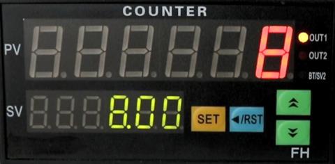
Digital counter is a LED control meter that can be used for counting (number/length/footage/batch/event/time), measuring (frequency/rotational speed/linear speed/flow) and position control. The most common way is to connect a digital counter with a photoelectric sensor or a rotary encoder to form a number counting system. The photoelectric sensor or rotary encoder outputs signal for counting number, and the digital counter displays the counting number. Another way, after the digital counter SV is set, once the counting number PV reaches SV, the digital counter internal relay will operate and alarm to realize process control.
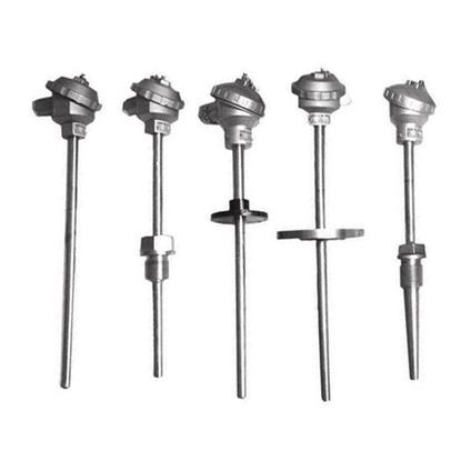
Industrial thermocouple and RTD protective casing are almost the same. Some temperature measuring elements are small in size, such as the armored type, and they also have similar shape. So, how to identify whether it is RTD or thermocouple without nameplate or unknowing the type? The following methods are listed to figure out the RTD and thermocouple for your reference.
Side blow of static contact and moving contact knife in closing
The fault cause is that the inappropriate position of static contact and moving contact knife causes side blow in closing. Check whether the fastening screw of moving contact knife of disconnect switch is too loose or too tight. Check whether the split ring on both sides of static contact of fuse type disconnect switch has movement or deforms or is damaged owing to poor contact, overheating or annealing.
Solution: adjust the degree of tightness and position between blades of fastening screw of level 3 moving contact, adjust the degree of tightness of moving contact knife, adjust moving contact knife to the center between moving contact knife and static contact, no side blow in closing test, no jam in closing. Fuse type disconnect switch adjusts the split ring on both sides of static contact to put the gap between static contacts at the center line of blades of moving contact knife. Then, conduct closing test.
1 Electromagnetic Design
For a common asynchronous motor, major performance parameters considered in design include the overload capacity, start performance ,efficiency and power. As for a VFD, its breakdown slip is inversely proportional to the power frequency, and it can start directly when the breakdown slip is near 1, therefore, the overload capacity and start performance doesn’t need to consider, the key problem to be solved is how to improve the adaptability of the motor to non sinusoidal power supplies. Methods are as follows:
Connect the positive and negative electrode of a 1.5~3V battery with the primary coil L1 and L2 of the transformer respectively, connect the transformer’s secondary side K1, K2 respectively with the positive and negative electrode of a milliammeter. After the loop is well connected, the indicator of milliammeter turns clockwise while connecting K, and turns anticlockwise while disconnecting K, that means the transformer's terminal connecting with the positive electrode of the battery has the same polarity with the terminal connecting with the positive end of the milliammeter, namely L1 and K1 have a same polarity and the transformer is a subtractive polarity. If the indicator turns conversely to the above, the transformer is an additive polarity.
Cause of current transformer burning up
- Secondary open circuit of the current transformer produces high voltage to burn out the current transformer.
- Long-term use of the current transformer makes the insulation aging, local breakdown or discharge occurs and overvoltage is thereof produced, thus burning out the current transformer.
- The aluminum contact surface of current transformer’s primary connection is seriously oxidized, which results in large contact resistance. The contact resistance gives out heats and burns out the current transformer
- Long-term overload operation makes the current transformer to give out heat, it is thereof burned out.
In industry, the pH meter is used more frequent as a pH measuring and analyzing instrument rather than the pH test paper and standard colour chart. The digital pH meter display screen can accurately show the pH value on real time, the error is greatly increased by one order of magnitude than that of pH test paper. Moreover, it can also realize the automatic control of pH value and pH value alarm. But due to the service life of pH electrodes, it is easy to break down, as a result, users have to pay much money in replace new pH electrodes. Next we will introduce the selection experience of pH electrode in several typical industries, so as to provide reference for users.
There should be no open circuit on the secondary side of the current transformer in operation. Once the open circuit occurs on the secondary side, high temperature caused by excessive iron loss may burn out the current transformer or enhance the voltage of secondary winding, thus breaking down the insulation and leading to the danger of high voltage electric shock. Therefore, when replacing a meter such as an ammeter, active power meter and reactive power meter, please ensure the current circuit in short circuit before operation. After replacement, connect the meter in the secondary circuit and then remove the short-circuit wires while checking if the meter is normal. In case sparks appear when removing the short-circuit wires, that means the current transformer disconnects, please short the loop again and confirm the meter loop isn’t an open circuit. When removing the short-circuit wires of the current transformer, please stand on an insulated pad and consider a protector to stop the current transformer loop. When it finishes work, the protector can be put in use.
A pH electrode is a part of the pH meter contacting with measured substance. It's used to measure the electrode potential. Generally, there are two methods to measure the pH value of the aqueous solutions, namely Colorimetry (pH test paper and cuvette) and potentiometric method. The latter is the only way to realize continuous on-line measurement and process monitoring. Moreover, it can obtain accurate and repeatable pH value. The electrode used in the potentiometric method is called as primary battery, which is a system used to converse the chemical reaction energy into electrical energy, voltage of the primary battery is called for electrodynamic force (EMF).
Machine vision has been favored by many industries, such as industrial production and scientific research, for its advantages in performance and imaging. However, clear and accurate imaging effect of machine vision is also inseparable from the imaging technology of industrial lens. It’s reported that factors affecting the imaging effect are the lens, aperture and depth of field. At present, what are mostly focused are basically two technical parameters, namely the aspherical lens and large depth of field. This paper mainly analyzes the effect of above two technologies on the imaging effect of machine vision.
UPS power system consists of 4 parts: rectification, energy storage, transformation and on-off control. UPS realizes the function of voltage stabilization with rectifier, which is generally a silicon-controlled rectifier (SCR) or high-frequency switching rectifier. The rectifier controls the output amplitude according to the change of external power supply; when the external power supply changes (the change should meet the system requirements), it outputs a rectified voltage whose amplitude keeps unchanged. Purification function of UPS is completed by the energy storage battery. As the rectifier cannot eliminate instantaneous pulse interference, the rectified voltage still has interference pulse. Energy storage battery can not only store DC power, but also plays a role of large-capacity capacitor for the rectifier, its equivalent capacitance is proportional to the capacity of energy storage battery. As the voltage at both ends of the capacitor can’t change suddenly, the pulse interference is eliminated due to the smoothness property of capacitor for pulses, thus realizing the purification, as well as the shielding against interference. Converter guarantees a stable frequency of uninterruptible power supply. Frequency stability is determined by the stability of the converter's oscillation frequency. To facilitate daily operation and maintenance of UPS power system, an operating switch, automatic bypass switch after fault self-checking, overhaul bypass switch are designed in this system.
There's no display on the panel after the UPS starts, UPS doesn't work?
Fault analysis: the fault may lie in power input, battery and power detection, battery voltage test circuit:
- Check if the power input fuse is burned out.
- If the fuse works normally, check whether the battery fuse is burned out, because some uninterruptible power supply may close all outputs and display when it can't detect a voltage.
- If the battery fuse is complete, please check if the power detection circuit works normally. If it doesn't work normally while UPS can't start without power supply, UPS will also close all outputs and display.
- If the power detection circuit works normally, please check if the battery voltage test circuit is normal.
- 2026
- 2025
- 2024
- 2023
- 2022
- 2021
- 2020
- 2019
- 2018
- 2017
- 2016
- 2015
- 2014
- 2013
- 2012