1 hp (0.75 kW) VFD, 3 Phase 230V, 400V, 480V

$206.49
Favorable price 1 hp (0.75 kW) VFD, three phase 230V/400V/480V 50Hz/60Hz for selection, sensorless vector variable frequency drive, RS485 enabled, strong overload capacity, manufacturer direct sale.
SKU: GK3000-4T0007G
Free Shipping
Delivery date: 6-12 days

1 hp variable frequency drive, three phase 50Hz/60Hz 220V, 230V, 240V, 380V, 400V, 415V, 480V, manufacturer direct sale.

Specification:

BasicsModelGK3000-4T0007G/ GK3000-2T0007G
Capacity1 hp (0.75 kW)
Shipping weight2 kg
Dimension190*104*150 mm for GK3000-4T0007G/ 236*130*176 mm for GK3000-2T0007G
I/O FeatureRated current2.1A at 380V ~ 480V, 3.8A at 220V ~ 240V
Input voltage3 phase 230V /400V /480V AC ±15% (Optional)
Input frequency50Hz/ 60Hz
Output voltage3 phase AC 0~input voltage
Output frequency0Hz~1000Hz
Over load capacity150% of rated current for 1 minute, 180% of rated current for 3 seconds
Control FeatureControl modeV/F control;
Sensorless vector control;
CommunicationRS485
Speed regulation1:100
Start torque150% of rating torque at 1 Hz
Speed control accuracy≤±0.5% of rating synchronous speed
Frequency precisionDigital setting: max frequency x± 0.01%;
Analog setting: max frequency x± 0.2%
Frequency resolutionAnalog setting: 0.1% of max frequency;
Digital setting: 0.01Hz
Torque boostAutomatic torque boost, manual torque boost 0.1%~30.0%
Interior PID controllerBe convenient to make closed-loop system
Automatic energy save runningOptimize V/F curve automatically based on the load to realize power save running
Automatic voltage regulation (AVR)Can keep constant output voltage when power source voltage varies.
Automatic current limitingLimit running current automatically to avoid frequent over-current which will cause trip
EnvironmentEnclosure ratingIP 20
Temperature–10℃~ +40℃; VFD will be derated if ambient temperature exceed 40℃; each rise 1℃, the derate will be 5%
Humidity5%-95%, without condensation
Altitude≤1000m; VFD will be derated if above 1000m
Impingement and oscillationNormal running:<5.9m/s2 (0.6g); Transportation:<15m/s2 (1.5g)
Store environment–20℃~ +60℃; no dust, no corrosive gas, no direct sunlight

Note: ATO VFD Cannot be used as a power source, it Can only be directly connected to an induction motor to control the motor speed.

Details
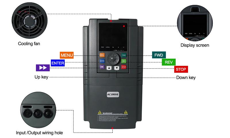
750W Three Phase VFD Details

Tips: Variable frequency drive heating problem treatments
The variable frequency drive will generate heat in operation due to internal loss, which the main circuit generates 98% and the control circuit 2%. In summer, the hot weather will raise the temperature of VFD to about 80~90℃. Because of VFD is an electronic device with electron device and electrolytic capacitor. The high temperature can cause components failure, LCD screen no display, and also cause VFD protection action. Therefore, must dissipate heat for VFD in order to extend the life of VFD.
General VFD operating ambient temperature is -10℃~+50℃. In order to ensure reliable operation of the VFD and extend the service life, VFD must perform heat dissipation. In winter, the built-in fan is able to drive the internal heat away. In summer, the temperature can reach 40℃, the built-in fan can only raise the indoor and VFD cabinet temperature. At this time the best way is to use the windows, or drill some φ500mm holes on the wall of the power distribution room near VFD, while ensuring in the cabinet around VFD there is some space, keeping natural ventilation. If this is still not enough, use built-in fan, or install exhaust fan and air flue around the holes to force out the heat. Moreover, the air conditioner can be the final solution for forced cooling.

How to Measure Circuits with a Digital Multimeter?

This video will show you how to measure electrical circuit using a digital multimeter.

VFD Two-Wire Control Wiring with Push Button for Forward Motor

In this video we've guided you through how to do VFD control wiring with a self-lock push button switch to run the motor in forward direction. We've covered everything from wiring to programming and even a test run. So just watch it through and hope you'll find it informative and helpful.

4-20mA speed Control on VFD

4-20mA is as common in analog control systems as 0~10V, and ATO GK3000 series VFDs are also perfectly compatible.

Product reviews
Perfect Shopping
5
Bell
Avatar
3/5/2019 7:42 PM
I received this 3 Phase variable frequency drive 3 days before. In these days, it works exactly beyond my expectation. This unit can run my 3 phase 60Hz grinder without any problem. I am satisfied with the service of this shop. Five stars given to this reliable 3 Phase VFD.
Was this review helpful? Yes No (0/0)
About the setting of VFD
5
Timothy
Avatar
8/18/2021 2:28 AM
How do I wire your variable frequency drive "GK3000" to restart automatically after power loss without using controls?
Was this review helpful? Yes No (0/0)
ATO Responded
You can do that, just set the VFD parameter P5.07=1, and test.
VFD parameter setting
5
Leicht
Avatar
9/14/2021 7:44 PM
Is there a setting to allow vfd to start at no less than 20hz every morning automatically, then produce as long as it can maintain freq. >20hz. Then shut off while awaiting more powerful sun condition without E.LU alarm that requires manual reset.
If the freq>20hz operational control is unachievable, any automatic start and stop without alarm requiring human reset interaction would be acceptable.
Was this review helpful? Yes No (0/0)
ATO Responded
1. Automatic start and stop setting, Set the VFD Parameters as follows:
P01.14=20(lower limit frequency)
P09.14=1(lower than the lower limit frequency to stop VFD)
2. When the VFD is faulted, automatically reset the fault EoL1, you can set the VFD Parameters as follows:
P05.03=0 (define DI4 terminal without function)
P05.02=9 (define DI3 terminal as RESET)
P06.02=2, (define relay output terminal TA1, TC1 as fault output)
P06.18=10.0 (output delay time)
Also, you need to use the cable to connect these terminals TA1 to DI3 and TC1 to COM, see attached wiring diagram for your reference.
will buy it again when I need it
5
Bily
Avatar
4/15/2022 1:46 AM
I JUST WANT TO SAY THAT OUT OF ALL VFDS I HAVE PURCHASED THIS ONE HAS WORKED SUPPER . No issues . I should have not listened to others and should have bought it . I would have saved 1000s. BELIEVE ME !!! THE USER MANUAL STATES HOW TO WIRE A SINGLE PHASE MOTOR EVEN WITH THE CAPPACITORS . I have used it with no issues and even showed to my friends who cannot believe the price and its functions . I will upload a video soon .
Was this review helpful? Yes No (0/0)
The play-by-play instructions of VFD
5
kolt
Avatar
3/2/2023 6:17 PM
As you can see under my fingers the air pressure sensor wires red to 24volt and black to CI. The second and third pictures all the Jumpers.
The instructions for the 50hz to 60hz worked perfect thanks. I would like to know if you could give me the play-by-play instructions like that for the pressure sensor parameters. By the compressor works perfect with no errors, just needs the commands to automatically start and stop.
Was this review helpful? Yes No (0/0)
ATO Responded
You can set parameters: P7.00=1, P7.26=1, P7.27=1.6, P7.05 is the set pressure.
What is wrong of VFD?
5
jesiah
Avatar
4/6/2023 1:57 AM
I ordered and installed a new ATO pressure sensor, thinking I had a bad sensor. I have it wired just like the diagram you sent. Please tell me what is wrong.
When I have P7.02 at 0, my compressor starts and runs up to 60.00 hz to perfectly builds air, but need sensor to shut down. When I put P7.02 at 6 for feedback for CI analog input (4-20 mA) and hit start, compressor will not start.
The hz meter is at 00.00hz, like settings do not signal to turn on. With the setting the way you informed me to get it to run at 60 hz and it does now perfect. But the rotary knob is inactive that I don't care I don't use that anyways.
Was this review helpful? Yes No (0/0)
ATO Responded
1. Please check whether the VFD feedback pressure (parameter b-15) is consistent with the actual pressure.
2. Please check whether the wiring of the sensor is correctly connected. For wiring, please refer to the attached document.
A problem of VFD
5
logan
Avatar
7/17/2023 3:29 AM
I still have a problem with the plc and vfd: they will not talk to each other fully.
Was this review helpful? Yes No (0/0)
ATO Responded
1. You can use the PLC digital output signal to control a relay, and then indirectly control the connection or disconnection of FWD and COM through the relay to realize VFD start/stop.
2. Our VFD can support 4-20ma/0-20ma input signal, you need to confirm whether the analog output of your PLC is 4-20ma or 0-20ma, connect it to the CI-GND terminal correctly, and set the JP3 jumper to I side.
For PLC/HMI control VFD, please refer to our demonstration video: https://www.youtube.com/watch?v=id1diuyTgE8&list=PLlo8RulDRnthBFbP4ydheukDSKw2hAfDn&index=19
3. VFD fault output uses relay output TA/TB/TC terminals, and the corresponding parameter is P4.12=15 (VFD fault). TA-TB is a normally open contact, and TA-TC is a normally closed contact, similar to a switch.
4. Please refer to the demonstration video of VFD 485 communication control: https://www.youtube.com/watch?v=D8ul5TyvlT4&list=PLlo8RulDRnthBFbP4ydheukDSKw2hAfDn&index=6
Can you please have an RMA for my VFD?
5
vikia
Avatar
7/27/2023 8:38 PM
Thank you for the response.
Can you please have an RMA for the two that I have purchased?
I will look into changing these units to three phases and contact you again in the future.
Was this review helpful? Yes No (0/0)
ATO Responded
Please provide us with the order number to further confirm what product you purchased. We need to know the exact model and parameters of the product you purchased in order to give you the correct advice, thank you for your understanding.
You do not need to return these 2 VFDs, because the VFDs you bought also support three-phase motors.
You only need to replace the single-phase motor with a three-phase motor of the same capacity, and the voltage is 220V/230V.
Is the VFD maximum output 50 Hz at P3.26?
5
nancy
Avatar
8/15/2023 12:39 AM
Hello Jason, one more thing. The programming seems to work perfectly and your second explanation got the fans running.
I appreciate all of that very much. However, at P3.26 the maximum output is 50 Hz on the system. Is there a way to override that to 60 or are we only able to go to 50 Hz?
Was this review helpful? Yes No (0/0)
ATO Responded
You can set VFD parameters P0.02=60, P0.06=60, P0.19=60, and test again.
VFD parameter setting information
5
heard
Avatar
8/28/2023 12:07 AM
Can you please highlight the parameter setting in the manual which allows for speed increase and decrease via terminals?
I couldn’t find any info on the manual you shared or in the video.
Was this review helpful? Yes No (0/0)
ATO Responded
Please refer to this quick set manual: https://www.ato.com/Content/doc/gk3000-series-vfd-quick-set-user-manual.pdf
Please set parameters P0.12, and P0.13 to increase and decrease speed.
replacement policy
5
jacob
Avatar
11/6/2023 12:57 AM
Hello
Purchased this unit from you a while back installed both the 1 and 3 HP together side by side started them up and
Ran them for over 7 min. and the 3HP started to smoke.
What is your replacement policy.
Attached is the order and pictures of the unit and manual.
Call me any time on the information.
Was this review helpful? Yes No (0/0)
ATO Responded
We also need the following information to proceed to the next step:
1. Please send us the nameplate label pictures of the VFD and motor, we want to see if the motor and VFD match each other?
2. Please send us a photo of the wiring diagram of the VFD input terminal, we want to confirm whether the VFD wiring is normal. Also, please tell us what is the voltage input to the VFD?
3. Could you remove the VFD cover and check whether the internal circuit board is burned? And please provide some photos for us to further confirm.
Practical VFD
5
Zenn
Avatar
5/13/2024 1:03 AM
We are working on a project and the customer sent a conveyor with the VFD wired up. The old machines we usually use safe torque to ensure safe operation. I don't know if this frequency converter has safe torque, and I also want to know more about this VFD.
Was this review helpful? Yes No (0/0)
ATO Responded
What is the safe torque of the inverter you mentioned? When the VFD triggers a switch signal, the VFD temporarily stops operating in a safe state and stops outputting torque to the motor. Is this what it means?
Our VFD can define braking commands through external multi-function terminals. When the braking command is triggered, the VFD automatically stops. Please send us a picture of the VFD nameplate label you received to our email address support@ato.com, and tell us what the specific control requirements are for your VFD.
Write your review
  • Only registered users can write reviews
*
*
  • Bad
  • Excellent
*
*
*
*

1 hp variable frequency drive, three phase 50Hz/60Hz 220V, 230V, 240V, 380V, 400V, 415V, 480V, manufacturer direct sale.

Specification:

BasicsModelGK3000-4T0007G/ GK3000-2T0007G
Capacity1 hp (0.75 kW)
Shipping weight2 kg
Dimension190*104*150 mm for GK3000-4T0007G/ 236*130*176 mm for GK3000-2T0007G
I/O FeatureRated current2.1A at 380V ~ 480V, 3.8A at 220V ~ 240V
Input voltage3 phase 230V /400V /480V AC ±15% (Optional)
Input frequency50Hz/ 60Hz
Output voltage3 phase AC 0~input voltage
Output frequency0Hz~1000Hz
Over load capacity150% of rated current for 1 minute, 180% of rated current for 3 seconds
Control FeatureControl modeV/F control;
Sensorless vector control;
CommunicationRS485
Speed regulation1:100
Start torque150% of rating torque at 1 Hz
Speed control accuracy≤±0.5% of rating synchronous speed
Frequency precisionDigital setting: max frequency x± 0.01%;
Analog setting: max frequency x± 0.2%
Frequency resolutionAnalog setting: 0.1% of max frequency;
Digital setting: 0.01Hz
Torque boostAutomatic torque boost, manual torque boost 0.1%~30.0%
Interior PID controllerBe convenient to make closed-loop system
Automatic energy save runningOptimize V/F curve automatically based on the load to realize power save running
Automatic voltage regulation (AVR)Can keep constant output voltage when power source voltage varies.
Automatic current limitingLimit running current automatically to avoid frequent over-current which will cause trip
EnvironmentEnclosure ratingIP 20
Temperature–10℃~ +40℃; VFD will be derated if ambient temperature exceed 40℃; each rise 1℃, the derate will be 5%
Humidity5%-95%, without condensation
Altitude≤1000m; VFD will be derated if above 1000m
Impingement and oscillationNormal running:<5.9m/s2 (0.6g); Transportation:<15m/s2 (1.5g)
Store environment–20℃~ +60℃; no dust, no corrosive gas, no direct sunlight

Note: ATO VFD Cannot be used as a power source, it Can only be directly connected to an induction motor to control the motor speed.

Details

750W Three Phase VFD Details

Tips: Variable frequency drive heating problem treatments
The variable frequency drive will generate heat in operation due to internal loss, which the main circuit generates 98% and the control circuit 2%. In summer, the hot weather will raise the temperature of VFD to about 80~90℃. Because of VFD is an electronic device with electron device and electrolytic capacitor. The high temperature can cause components failure, LCD screen no display, and also cause VFD protection action. Therefore, must dissipate heat for VFD in order to extend the life of VFD.
General VFD operating ambient temperature is -10℃~+50℃. In order to ensure reliable operation of the VFD and extend the service life, VFD must perform heat dissipation. In winter, the built-in fan is able to drive the internal heat away. In summer, the temperature can reach 40℃, the built-in fan can only raise the indoor and VFD cabinet temperature. At this time the best way is to use the windows, or drill some φ500mm holes on the wall of the power distribution room near VFD, while ensuring in the cabinet around VFD there is some space, keeping natural ventilation. If this is still not enough, use built-in fan, or install exhaust fan and air flue around the holes to force out the heat. Moreover, the air conditioner can be the final solution for forced cooling.

Product reviews
Perfect Shopping
5
Bell
Avatar
3/5/2019 7:42 PM
I received this 3 Phase variable frequency drive 3 days before. In these days, it works exactly beyond my expectation. This unit can run my 3 phase 60Hz grinder without any problem. I am satisfied with the service of this shop. Five stars given to this reliable 3 Phase VFD.
Was this review helpful? Yes No (0/0)
About the setting of VFD
5
Timothy
Avatar
8/18/2021 2:28 AM
How do I wire your variable frequency drive "GK3000" to restart automatically after power loss without using controls?
Was this review helpful? Yes No (0/0)
ATO Responded
You can do that, just set the VFD parameter P5.07=1, and test.
VFD parameter setting
5
Leicht
Avatar
9/14/2021 7:44 PM
Is there a setting to allow vfd to start at no less than 20hz every morning automatically, then produce as long as it can maintain freq. >20hz. Then shut off while awaiting more powerful sun condition without E.LU alarm that requires manual reset.
If the freq>20hz operational control is unachievable, any automatic start and stop without alarm requiring human reset interaction would be acceptable.
Was this review helpful? Yes No (0/0)
ATO Responded
1. Automatic start and stop setting, Set the VFD Parameters as follows:
P01.14=20(lower limit frequency)
P09.14=1(lower than the lower limit frequency to stop VFD)
2. When the VFD is faulted, automatically reset the fault EoL1, you can set the VFD Parameters as follows:
P05.03=0 (define DI4 terminal without function)
P05.02=9 (define DI3 terminal as RESET)
P06.02=2, (define relay output terminal TA1, TC1 as fault output)
P06.18=10.0 (output delay time)
Also, you need to use the cable to connect these terminals TA1 to DI3 and TC1 to COM, see attached wiring diagram for your reference.
will buy it again when I need it
5
Bily
Avatar
4/15/2022 1:46 AM
I JUST WANT TO SAY THAT OUT OF ALL VFDS I HAVE PURCHASED THIS ONE HAS WORKED SUPPER . No issues . I should have not listened to others and should have bought it . I would have saved 1000s. BELIEVE ME !!! THE USER MANUAL STATES HOW TO WIRE A SINGLE PHASE MOTOR EVEN WITH THE CAPPACITORS . I have used it with no issues and even showed to my friends who cannot believe the price and its functions . I will upload a video soon .
Was this review helpful? Yes No (0/0)
The play-by-play instructions of VFD
5
kolt
Avatar
3/2/2023 6:17 PM
As you can see under my fingers the air pressure sensor wires red to 24volt and black to CI. The second and third pictures all the Jumpers.
The instructions for the 50hz to 60hz worked perfect thanks. I would like to know if you could give me the play-by-play instructions like that for the pressure sensor parameters. By the compressor works perfect with no errors, just needs the commands to automatically start and stop.
Was this review helpful? Yes No (0/0)
ATO Responded
You can set parameters: P7.00=1, P7.26=1, P7.27=1.6, P7.05 is the set pressure.
What is wrong of VFD?
5
jesiah
Avatar
4/6/2023 1:57 AM
I ordered and installed a new ATO pressure sensor, thinking I had a bad sensor. I have it wired just like the diagram you sent. Please tell me what is wrong.
When I have P7.02 at 0, my compressor starts and runs up to 60.00 hz to perfectly builds air, but need sensor to shut down. When I put P7.02 at 6 for feedback for CI analog input (4-20 mA) and hit start, compressor will not start.
The hz meter is at 00.00hz, like settings do not signal to turn on. With the setting the way you informed me to get it to run at 60 hz and it does now perfect. But the rotary knob is inactive that I don't care I don't use that anyways.
Was this review helpful? Yes No (0/0)
ATO Responded
1. Please check whether the VFD feedback pressure (parameter b-15) is consistent with the actual pressure.
2. Please check whether the wiring of the sensor is correctly connected. For wiring, please refer to the attached document.
A problem of VFD
5
logan
Avatar
7/17/2023 3:29 AM
I still have a problem with the plc and vfd: they will not talk to each other fully.
Was this review helpful? Yes No (0/0)
ATO Responded
1. You can use the PLC digital output signal to control a relay, and then indirectly control the connection or disconnection of FWD and COM through the relay to realize VFD start/stop.
2. Our VFD can support 4-20ma/0-20ma input signal, you need to confirm whether the analog output of your PLC is 4-20ma or 0-20ma, connect it to the CI-GND terminal correctly, and set the JP3 jumper to I side.
For PLC/HMI control VFD, please refer to our demonstration video: https://www.youtube.com/watch?v=id1diuyTgE8&list=PLlo8RulDRnthBFbP4ydheukDSKw2hAfDn&index=19
3. VFD fault output uses relay output TA/TB/TC terminals, and the corresponding parameter is P4.12=15 (VFD fault). TA-TB is a normally open contact, and TA-TC is a normally closed contact, similar to a switch.
4. Please refer to the demonstration video of VFD 485 communication control: https://www.youtube.com/watch?v=D8ul5TyvlT4&list=PLlo8RulDRnthBFbP4ydheukDSKw2hAfDn&index=6
Can you please have an RMA for my VFD?
5
vikia
Avatar
7/27/2023 8:38 PM
Thank you for the response.
Can you please have an RMA for the two that I have purchased?
I will look into changing these units to three phases and contact you again in the future.
Was this review helpful? Yes No (0/0)
ATO Responded
Please provide us with the order number to further confirm what product you purchased. We need to know the exact model and parameters of the product you purchased in order to give you the correct advice, thank you for your understanding.
You do not need to return these 2 VFDs, because the VFDs you bought also support three-phase motors.
You only need to replace the single-phase motor with a three-phase motor of the same capacity, and the voltage is 220V/230V.
Is the VFD maximum output 50 Hz at P3.26?
5
nancy
Avatar
8/15/2023 12:39 AM
Hello Jason, one more thing. The programming seems to work perfectly and your second explanation got the fans running.
I appreciate all of that very much. However, at P3.26 the maximum output is 50 Hz on the system. Is there a way to override that to 60 or are we only able to go to 50 Hz?
Was this review helpful? Yes No (0/0)
ATO Responded
You can set VFD parameters P0.02=60, P0.06=60, P0.19=60, and test again.
VFD parameter setting information
5
heard
Avatar
8/28/2023 12:07 AM
Can you please highlight the parameter setting in the manual which allows for speed increase and decrease via terminals?
I couldn’t find any info on the manual you shared or in the video.
Was this review helpful? Yes No (0/0)
ATO Responded
Please refer to this quick set manual: https://www.ato.com/Content/doc/gk3000-series-vfd-quick-set-user-manual.pdf
Please set parameters P0.12, and P0.13 to increase and decrease speed.
replacement policy
5
jacob
Avatar
11/6/2023 12:57 AM
Hello
Purchased this unit from you a while back installed both the 1 and 3 HP together side by side started them up and
Ran them for over 7 min. and the 3HP started to smoke.
What is your replacement policy.
Attached is the order and pictures of the unit and manual.
Call me any time on the information.
Was this review helpful? Yes No (0/0)
ATO Responded
We also need the following information to proceed to the next step:
1. Please send us the nameplate label pictures of the VFD and motor, we want to see if the motor and VFD match each other?
2. Please send us a photo of the wiring diagram of the VFD input terminal, we want to confirm whether the VFD wiring is normal. Also, please tell us what is the voltage input to the VFD?
3. Could you remove the VFD cover and check whether the internal circuit board is burned? And please provide some photos for us to further confirm.
Practical VFD
5
Zenn
Avatar
5/13/2024 1:03 AM
We are working on a project and the customer sent a conveyor with the VFD wired up. The old machines we usually use safe torque to ensure safe operation. I don't know if this frequency converter has safe torque, and I also want to know more about this VFD.
Was this review helpful? Yes No (0/0)
ATO Responded
What is the safe torque of the inverter you mentioned? When the VFD triggers a switch signal, the VFD temporarily stops operating in a safe state and stops outputting torque to the motor. Is this what it means?
Our VFD can define braking commands through external multi-function terminals. When the braking command is triggered, the VFD automatically stops. Please send us a picture of the VFD nameplate label you received to our email address support@ato.com, and tell us what the specific control requirements are for your VFD.
Only registered users can write reviews
Customers who bought this item also bought

1 hp (0.75 kW) VFD, Single Phase Input & Output

GK3000-1S0007
$195.82
Affordable 1 hp VFD, 1 phase for single phase AC induction motor, 220V - 240V 7 amps, manufacturer direct sale.

2 hp (1.5 kW) VFD, 3 Phase 240V, 415V, 480V

GK3000-4T0015G
$218.41
Cheap price 2 hp (1.5 kW) VFD, three phase 240V, 415V, 480V for choice, brand new sensorless vector variable frequency drive, RS485 enabled, strong overload capacity, manufacturer direct sale.

7.5 hp (5.5 kW) VFD, 3 Phase 208V, 380V, 480V

GK3000-4T0055G
$415.08
7.5 hp (5.5 kW) VFD with wholesale price, 3 phase 208V/380V/480V 50Hz/60Hz for option, heavy duty variable frequency drive, 13 amps at 380V ~480V, strong overload capacity, manufacturer direct sale.

15 hp (11 kW) VFD, 3 Phase 230V, 415V, 480V

GK3000-4T0110G
$634.44
Inexpensive 15 hp (11 kW) VFD, three phase 230V/415V/480V, high performance variable frequency drive, IP20 enclosure, RS485 enabled, brand new direct sale by manufacturer in China.

1 hp (0.75kW) 3 phase 4 pole AC Induction Motor

ATO-IM-7504P
$409.52
Three-phase AC induction motor or asynchronous motor for sale, 1 hp or 0.75kW rated output, 4-pole number, 1390rpm rated speed, and rated voltages 380V 50Hz. Cheap 3-phase induction motor is designed with optimum structure, high reliability, low noise and convenient to operate.