
1hp variable frequency drive, single phase to three phase VFD, 220V AC, 0-1000Hz.
Specification:
| Basics | Model | GK3000-2S0007 |
| Capacity | 1 hp (0.75 kW) | |
| Shipping weight | 2 kg | |
| Dimension | 142*85*113 mm | |
| I/O Feature | Rated current | 4 A |
| Input voltage | 1 phase 220~240V AC | |
| Input frequency | 50Hz/ 60Hz | |
| Output voltage | 3 phase AC 0~input voltage | |
| Output frequency | 0Hz~1000Hz | |
| Over load capacity | 150% of rated current for 1 minute, 180% of rated current for 3 seconds | |
| Control Feature | Control mode | V/F, Sensorless vector control (SVC), Speed sensor vector control (FVC) |
| Communication | RS485 | |
| Speed regulation | 1:100 | |
| Start torque | 150% of rating torque at 1 Hz | |
| Speed control accuracy | ≤±0.5% of rating synchronous speed | |
| Frequency precision | Digital setting: max frequency x± 0.01%; Analog setting: max frequency x± 0.2% | |
| Frequency resolution | Analog setting: 0.1% of max frequency; Digital setting: 0.01Hz | |
| Torque boost | Automatic torque boost, manual torque boost 0.1%~30.0% | |
| Interior PID controller | Be convenient to make closed-loop system | |
| Automatic energy save running | Optimize V/F curve automatically based on the load to realize power save running | |
| Automatic voltage regulation (AVR) | Can keep constant output voltage when power source voltage varies. | |
| Automatic current limiting | Limit running current automatically to avoid frequent over-current which will cause trip | |
| Environment | Enclosure rating | IP 20 |
| Temperature | –10℃~ +40℃; VFD will be derated if ambient temperature exceed 40℃; each rise 1℃, the derate will be 5% | |
| Humidity | 5%-95%, without condensation | |
| Altitude | ≤1000m; VFD will be derated if above 1000m | |
| Impingement and oscillation | Normal running:<5.9m/s2 (0.6g); Transportation:<15m/s2 (1.5g) | |
| Store environment | –20℃~ +60℃; no dust, no corrosive gas, no direct sunlight |
Note: ATO VFD Cannot be used as a power source, it Can only be directly connected to an induction motor to control the motor speed.
Details
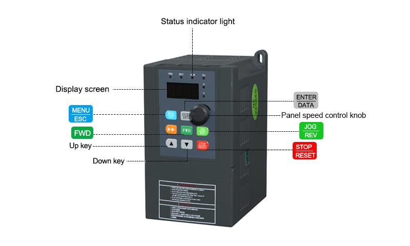
Tips: Variable frequency drive condensation eliminating methods
By the impact of air humidity, once the working environment temperature changes greatly, VFD may appear condensation phenomenon and causing liquid water appear on the internal power devices, circuit boards and other parts. The water will produce corresponding conductive channel with the dust, and then the electrical insulating property of VFD will be reduced and even produce short circuit, electronic components failure and other problems.
Elimination of condensation:
- Temperature control
Setting a filter on the vent can not only preventing a lot of dust into VFD, but also can ensure IP protection level. When the temperature exceeds 40℃, it will start the ventilation system. When the relative humidity exceeds 80%, it will start the heater. Or VFD is completely sealed, effectively putting an end to the salt spray, harmful gases and dust into VFD. - Humidity control
1) Temperature difference dehumidification method: Install the radiator which is conducive to formation condensation inside VFD, so that the other parts will not form condensation. The condensate formed on the radiator will be discharged through the outlet to ensure that VFD is always maintained relatively dry.
2) Adsorption and membrane dehumidification method: Set the appropriate adsorption material in VFD for water vapor adsorption to ensure relatively dry environment in VFD. It can also be set with the membrane filter to barrier the water vapor, only allow dry air to pass through the filter so that only relatively dry air can flow into VFD.
3) Condensation dehumidification method: Set the lowest temperature point inside VFD to let the condensation only generated there, so that to effectively reduce inside relative humidity and making VFD always maintain a relatively dry environment.

I'm very new to electrical wiring so I'm a bit confused on a few things. Typically green wires are the ground wires, and the green wire in this case goes inside the VFD itself, so I'm not sure where it's attached to. On the external wiring part, there's a screw labeled "E" which in the manual is the ground. Is this green wire the ground wire, just grounded internally? So I wouldn't need to attach a wire to the external "E" screw to ground it? The VFD also came with 1 red wire, which was attached to the "R" screw. There was then another small red wire that ran from the "R" screw to the "S" screw", then another red wire from "S" to "T". I understand this to be the input power to the VFD, and the U, V, and W screws are the 3-phase 230v output that'' connect to the motor. Most videos I've watched show a red wire and a black wire connected to the R and S screws for 120v 1-phase input. But in the case of the VFD wiring the way it came it's the red wire basically attached to the R, S, and T screws. I just wanted to make sure that there wasn't another wire necessary, and to clarify which of the R, S, and T screws the wires should be attached to for 1-phase 120v input. We planned to plug it into a wall outlet using just a typical 2 prong male connector. Is that how we should plug it in as well?
We are trying to program the unit for single phase in and three phase to the motor. We can send specifics on the motor if that would help us get this programmed. The motor is running hot and the unit is making a grinding noise. We ran an Allen-Bradley Powerflex 4 in the past and it worked like a champ. We have the manual and a fairly experienced program guy, but we can't make the changes the manual is telling him to make.

2 hp VFD, Single Phase to Three Phase VFD

3 hp VFD, Single Phase to Three Phase VFD

5 hp VFD, Single Phase to Three Phase VFD

25 hp VFD, 1-Phase 220V to 3-Phase 380V VFD

2 Pole Molded Case Circuit Breaker, 20A/ 30A/ 40A/ 50A to 100A

1/2 hp VFD, Single Phase to Three Phase VFD

1 hp (0.75 kW) VFD, 3 Phase 230V, 400V, 480V

1 hp (0.75 kW) VFD, Single Phase Input & Output