Inclinometer Sensor, Output Modbus, ±10°~±90°

$192.31
Single axis or dual axis inclinometer sensor for sale. High precision tilt switch comes with output signal Modbus, optional measuring range ±10°/±30°/±60°/±90°, output interface RS232, RS485, RS232, UART TTL, absolute accuracy 0.05°, power supply input 9-36V.
SKU: ATO-IMS-116126MB
*
*
*
Free Shipping
Delivery date: 6-12 days

Cheap industrial inclinometer sensor features 1-axis/2-axis, Modbus output, output interface RS232, RS485, RS232, UART TTL, and optional measuring range±10°~±90°. It is an industrial tilt switch sensor with reliable, stable performance and good scalability, suitable for various harsh control environments.

Features

  • The Modbus inclinometer sensor uses RS485 hardware differential bus to transmit data, single axis or dual axis is available.
  • The tilt sensor has a built-in high-precision 16 bit A/D differential converter, which can measure the tilt and pitch angle of the sensor output relative to the horizontal plane through a 5-order filtering algorithm.
  • Due to the built-in high-precision digital temperature sensor, the inclinometer sensor can correct the temperature drift according to the temperature value change, ensuring the high repeatability of the tilt sensor, in low and high temperature environments.
  • The output response frequency standard of the inclinometer sensor can reach 18Hz. If you need a higher response frequency, you can contact us for customization.

Technical Specification

ModelATO-SCA116M-MB/SCA126M-MBCondition
Measuring AxisX/XY (single/dual)X/XY (single/dual)X/XY (single/dual)X/XY (single/dual)-
Measuring Range*±10°±30°±60°±90°-
Resolution0.01°0.01°0.02°0.03°-
Absolute Accuracy0.05°0.05°0.05°0.05°@25℃
Long Term Stability0.05°0.05°0.05°0.05°-
Zero Temperature Coefficient±0.006°/℃±0.006°/℃±0.006°/℃±0.006°/℃-40~85℃
Sensitivity Temperature Coefficient≤100 ppm/℃≤100 ppm/℃≤100 ppm/℃≤100 ppm/℃-40~85℃
Power On Time0.5s0.5s0.5s0.5s-
Response Time0.02s0.02s0.02s0.02s-
Response Frequency5Hz, 15Hz, 35Hz, 50Hz for set
Output SignalModbus
Electromagnetic CompatibilityAccording to EN61000 and GBT17626
MTBF≥50000 hours/times
Insulation Resistance≥100MΩ
Shockproof100g@11ms, 3 Times/Axis (half sinusoid))
Anti-Vibration10grms, 10~1000Hz
Protection GradeIP67
High Seismic Performance>2000g
CablesStandard 1m length, wearproof, grease proofing, wide temperature, shielded cables 4*0.4mm2
Dimension46*35.4*13.6mm
Weight165g (without cable)

*Note: This Technical data only list ±10°, ±30°, ±60°, ±90° series for reference, other measuring range please refer to the adjacent specifications.

Electrical Specification

ItemMinStandardMaxCondition
Power Supply9V12V, 24V36VStandard
-5V-Customizable
Working Current-42mA-5V
-26mA-12V
-17mA-24V
Working Temperature-40℃-+85℃-
Store Temperature-55℃-+125℃-

Modbus Inclinometer Sensor Electrical Wiring

  • RS485 Wiring Definition
Line Color FunctionBLACKWHITEGREENRED
GND
Power negative
RS485 (D+)RS485 (D-)Vcc 9~36V
Power positive
  • RS232/TTL Wiring Definition
Line Color FunctionBLACKWHITEGREENRED
GND
Power negative
RS232 (RXD)
/TTL (RXD)
RS232 (RXD)
/TTL (RXD)
Vcc 9~36V
Power positive
  • RS422 Wiring Definition
Line Color FunctionREDORANGEYELLOWBLUEPURPLEBLACK
GND
Power positive
TXD+RXD-RXD+TXD-GND
Power negative

Modbus Inclinometer Sensor Dimensions Diagram
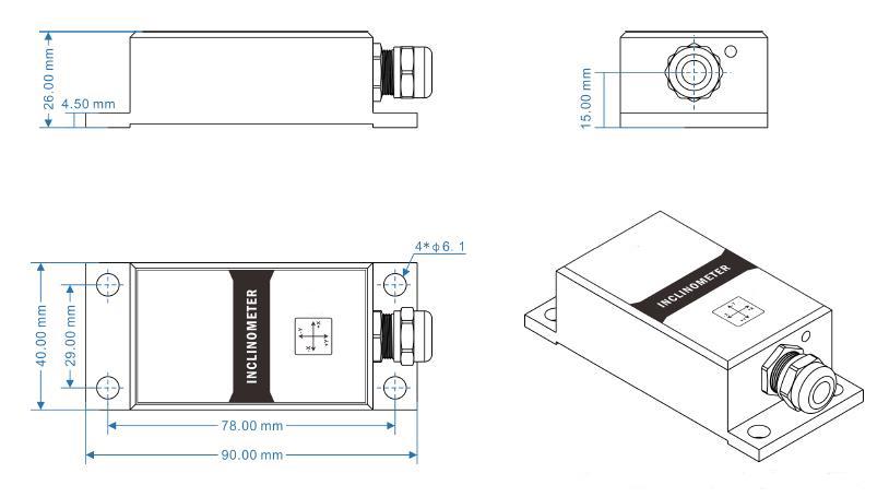
Dimensions of modbus inclinometer sensor 10°-90°

Inclinometer Sensor Installation Direction Diagram

The installation must guarantee the inclinometer sensor bottom is parallel to measured face,and reduce the influence of dynamic and acceleration to the tilt sensor. This inclinometer sensor can be installed horizontally or mounted vertically, for installation please refer to the following scheme.
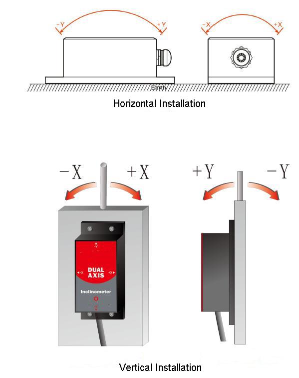
Installation Diagram of modbus inclinometer sensor 10°-90°

Tips: Inclinometer sensor working principle.

Inclinometer sensor uses high-performance core control unit, using the principle of capacitive miniature pendulum. Inclinometer sensor uses the principle of earth's gravity. When the inclination unit is tilted, the earth's gravity will produce a component of gravity on the corresponding pendulum, and the corresponding capacitance will change. The inclination angle is obtained by amplifying, filtering, and converting the capacitance.
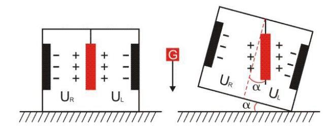
Inclinometer Sensor Working Principle

As shown in the figure, UL is the voltage between the left plate of the pendulum and its corresponding electrode, and UR is the voltage between the right plate and its corresponding electrode. When the inclinometer sensor is tilted, UL and UR will change according to a certain rule. Therefore, ξ (UL, UR) is a function of the inclination angle α: α = ξ (UL, UR)

In this video, ATO will show you top ten most used sensors (sensing technologies).

Product reviews
Convenient, works well
5
Edwin
Avatar
5/6/2022 3:54 AM
Recently, our company is conducting on-site survey of the computer room construction. We have high requirements for accuracy and we have bought several other brands before, but the accuracy is not enough. This one has high accuracy, good quality and low price. It works well and is convenient. We will definitely buy these again.
Was this review helpful? Yes No (0/0)
About power supply
5
Reedy
Avatar
7/5/2024 3:09 AM
The distance from the display panel to a 120 VAC connection is 2 meters, so the default 1 meter power cable for the display panel should work. Can you supply the DC9-36V power supply for the panel display? The distance from the display panel to the sensor is 25 meters, so 2 additional cable extensions will be required. Would you suggest extension cables to do this or can you provide longer cables from the sensors?
Was this review helpful? Yes No (0/0)
ATO Responded
1. If your power supply is only 120VAC, then you need to configure a switching power supply to convert 120VAC to 24VDC, and then supply power to the display panel through the 24V switching power supply. We recommend this switching power supply 24V/50W switching power supply, SKU: ATO-SMPS-50-24, input voltage 85~132VAC, output voltage 24VDC, see spec on: https://www.ato.com/24v-dc-2-1a-50w-switching-power-supply
2. Yes, we can provide longer sensor cables, 25 meters long sensor cables, including 2 meters long display panel power cables. However, you will need to configure the cable for the switching power supply yourself. Specifically, you need to provide the 120VAC power cable and connect it to the 24V switching power cable.
Write your review
  • Only registered users can write reviews
*
*
  • Bad
  • Excellent
*
*
*
*

Cheap industrial inclinometer sensor features 1-axis/2-axis, Modbus output, output interface RS232, RS485, RS232, UART TTL, and optional measuring range±10°~±90°. It is an industrial tilt switch sensor with reliable, stable performance and good scalability, suitable for various harsh control environments.

Features

  • The Modbus inclinometer sensor uses RS485 hardware differential bus to transmit data, single axis or dual axis is available.
  • The tilt sensor has a built-in high-precision 16 bit A/D differential converter, which can measure the tilt and pitch angle of the sensor output relative to the horizontal plane through a 5-order filtering algorithm.
  • Due to the built-in high-precision digital temperature sensor, the inclinometer sensor can correct the temperature drift according to the temperature value change, ensuring the high repeatability of the tilt sensor, in low and high temperature environments.
  • The output response frequency standard of the inclinometer sensor can reach 18Hz. If you need a higher response frequency, you can contact us for customization.

Technical Specification

ModelATO-SCA116M-MB/SCA126M-MBCondition
Measuring AxisX/XY (single/dual)X/XY (single/dual)X/XY (single/dual)X/XY (single/dual)-
Measuring Range*±10°±30°±60°±90°-
Resolution0.01°0.01°0.02°0.03°-
Absolute Accuracy0.05°0.05°0.05°0.05°@25℃
Long Term Stability0.05°0.05°0.05°0.05°-
Zero Temperature Coefficient±0.006°/℃±0.006°/℃±0.006°/℃±0.006°/℃-40~85℃
Sensitivity Temperature Coefficient≤100 ppm/℃≤100 ppm/℃≤100 ppm/℃≤100 ppm/℃-40~85℃
Power On Time0.5s0.5s0.5s0.5s-
Response Time0.02s0.02s0.02s0.02s-
Response Frequency5Hz, 15Hz, 35Hz, 50Hz for set
Output SignalModbus
Electromagnetic CompatibilityAccording to EN61000 and GBT17626
MTBF≥50000 hours/times
Insulation Resistance≥100MΩ
Shockproof100g@11ms, 3 Times/Axis (half sinusoid))
Anti-Vibration10grms, 10~1000Hz
Protection GradeIP67
High Seismic Performance>2000g
CablesStandard 1m length, wearproof, grease proofing, wide temperature, shielded cables 4*0.4mm2
Dimension46*35.4*13.6mm
Weight165g (without cable)

*Note: This Technical data only list ±10°, ±30°, ±60°, ±90° series for reference, other measuring range please refer to the adjacent specifications.

Electrical Specification

ItemMinStandardMaxCondition
Power Supply9V12V, 24V36VStandard
-5V-Customizable
Working Current-42mA-5V
-26mA-12V
-17mA-24V
Working Temperature-40℃-+85℃-
Store Temperature-55℃-+125℃-

Modbus Inclinometer Sensor Electrical Wiring

  • RS485 Wiring Definition
Line Color FunctionBLACKWHITEGREENRED
GND
Power negative
RS485 (D+)RS485 (D-)Vcc 9~36V
Power positive
  • RS232/TTL Wiring Definition
Line Color FunctionBLACKWHITEGREENRED
GND
Power negative
RS232 (RXD)
/TTL (RXD)
RS232 (RXD)
/TTL (RXD)
Vcc 9~36V
Power positive
  • RS422 Wiring Definition
Line Color FunctionREDORANGEYELLOWBLUEPURPLEBLACK
GND
Power positive
TXD+RXD-RXD+TXD-GND
Power negative

Modbus Inclinometer Sensor Dimensions Diagram

Dimensions of modbus inclinometer sensor 10°-90°

Inclinometer Sensor Installation Direction Diagram

The installation must guarantee the inclinometer sensor bottom is parallel to measured face,and reduce the influence of dynamic and acceleration to the tilt sensor. This inclinometer sensor can be installed horizontally or mounted vertically, for installation please refer to the following scheme.

Installation Diagram of modbus inclinometer sensor 10°-90°

Tips: Inclinometer sensor working principle.

Inclinometer sensor uses high-performance core control unit, using the principle of capacitive miniature pendulum. Inclinometer sensor uses the principle of earth's gravity. When the inclination unit is tilted, the earth's gravity will produce a component of gravity on the corresponding pendulum, and the corresponding capacitance will change. The inclination angle is obtained by amplifying, filtering, and converting the capacitance.

Inclinometer Sensor Working Principle

As shown in the figure, UL is the voltage between the left plate of the pendulum and its corresponding electrode, and UR is the voltage between the right plate and its corresponding electrode. When the inclinometer sensor is tilted, UL and UR will change according to a certain rule. Therefore, ξ (UL, UR) is a function of the inclination angle α: α = ξ (UL, UR)

Product reviews
Convenient, works well
5
Edwin
Avatar
5/6/2022 3:54 AM
Recently, our company is conducting on-site survey of the computer room construction. We have high requirements for accuracy and we have bought several other brands before, but the accuracy is not enough. This one has high accuracy, good quality and low price. It works well and is convenient. We will definitely buy these again.
Was this review helpful? Yes No (0/0)
About power supply
5
Reedy
Avatar
7/5/2024 3:09 AM
The distance from the display panel to a 120 VAC connection is 2 meters, so the default 1 meter power cable for the display panel should work. Can you supply the DC9-36V power supply for the panel display? The distance from the display panel to the sensor is 25 meters, so 2 additional cable extensions will be required. Would you suggest extension cables to do this or can you provide longer cables from the sensors?
Was this review helpful? Yes No (0/0)
ATO Responded
1. If your power supply is only 120VAC, then you need to configure a switching power supply to convert 120VAC to 24VDC, and then supply power to the display panel through the 24V switching power supply. We recommend this switching power supply 24V/50W switching power supply, SKU: ATO-SMPS-50-24, input voltage 85~132VAC, output voltage 24VDC, see spec on: https://www.ato.com/24v-dc-2-1a-50w-switching-power-supply
2. Yes, we can provide longer sensor cables, 25 meters long sensor cables, including 2 meters long display panel power cables. However, you will need to configure the cable for the switching power supply yourself. Specifically, you need to provide the 120VAC power cable and connect it to the 24V switching power cable.
Only registered users can write reviews
Customers who bought this item also bought

2D Electronic Compass Sensor, 0°-360°, RS232/RS485/TTL/RS422

ATO-CPS-SCM225
$193.47
Buy 2D electronic compass sensor online with a measurement range of 0° to 360° and an accuracy of ±1°. The compass sensor supports multiple communication interfaces including RS232, RS485, TTL, RS422 and Modbus. It has a wide operating temperature range from -40℃ to +70℃.

Diffuse Reflective Photoelectric Sensor

ATO-PHOS-DR
$59.27
Diffuse reflective photoelectric sensor consists of light projector and light receiver in one, can distinguish transparent or opaque reflective object. The supply voltage is DC 12V-24V (6-36V) or AC 110V-220V (90-250V). Infrared photoelectric sensor can be compensated for longer distance with sensitivity controller, less susceptible to interference, fast reaction, long life, high resolution and high reliability.

DC Current Sensor 50A/100A/200A/500A/1000A to 1500A

ATO-CUS-DC1500
$83.25
Hall effect DC current sensors are open loop current sensors, with split-core structure, 1ms fast response time, 1.0%FS accuracy, 4-20mA output signal, 12V/24V power supply, fixed installation, excellent linearity and strong anti-interference capacity. DC current sensors are widely used for DC current monitoring, system signal acquisition and feedback control.

Isolated DC Voltage Sensor 10mV to 1000V, Power Supply DC 12V/24V

ATO-VOS-DC1000
$141.96
DC voltage sensor uses modulation and demodulation technology to achieve input/output/power supply isolation. Isolated voltage transducer has measuring range from DC 10mV/50mV/75mV/5V/150V/300V/500V to 1000V, supply voltage DC 12V/24V, accuracy 0.2%FS, output signal 0-5V/0-10V/0-20mA/4-20mA and strong anti-interference capability. DC voltage sensor is widely used for voltage isolated measuring and control, such as electric power, remote monitoring, medical equipment, etc.

1200W Industrial Air Blower, Variable Speed, 110V/220V

ATO-ABL-1200
$868.23
Small industrial air blower for sale, 1200 Watt, 110V/220V AC, designed for air vacuum and air blower with stable air volume, air flow available with 253m3/h (148 CFM), 240m3/h (140 CFM) and 228m3/h (134 CFM). The blower has 44.5 mm inlet & outlet diameter, and max. speed 20000 RPM, allowing variable speed to realize the air volume adjustable. High pressure, steady airflow and favorable price.