
Torque sensors have capacity range from 2 Nm, 5 Nm, 10 Nm, 20 Nm, 30 Nm, 50 Nm, 100 Nm to 2000Nm. Torque sensor capacity can be customized according to customer requirements. After purchasing one ATO torque sensor, you can buy a special digital panel meter to obtain readings directly, or buy a matched transmitter to output standard signal to PLC, DCS and other systems. Customized output signal is 0~5V, 0~10V, 0~±10V, or 4-20mA.
Specification
| Model | ATO-DYJN-103 |
| Shipping Weight | 1.5kg |
| Capacity Range * | 0-2000 Nm (Contact us for your specific capacity) |
| Sensitivity | 1.0-2.0mV/V |
| With Transmitter | ATO-LCTR-OAR |
| Accuracy | 0.3%FS |
| Zero Balance | ±2%FS |
| Non-linearity | 0.2%FS |
| Hysteresis | 0.05%FS |
| Repeatability | 0.05%FS |
| Creep | 0.05%FS/30min |
| Temperature Drift on Zero | <0.05%F.S/10℃ |
| Temperature Effect on output | <0.05%F.S/10℃ |
| Operating Temperature | -20℃~+80℃ |
| Humidity | 0~90%RH |
| Impedance | 350Ω |
| Insulation Resistance | ≥5000MΩ/100VDC |
| Stability | 0.3%FS/year |
| Safety Overload | 120%F.S |
| Ultimate Overload | 150%F.S |
| Excitation Voltage | DC 5-15V |
| Material | Alloy steel |
| Protection Class | IP65 |
| Cable Length | 3m (Φ3mm) |
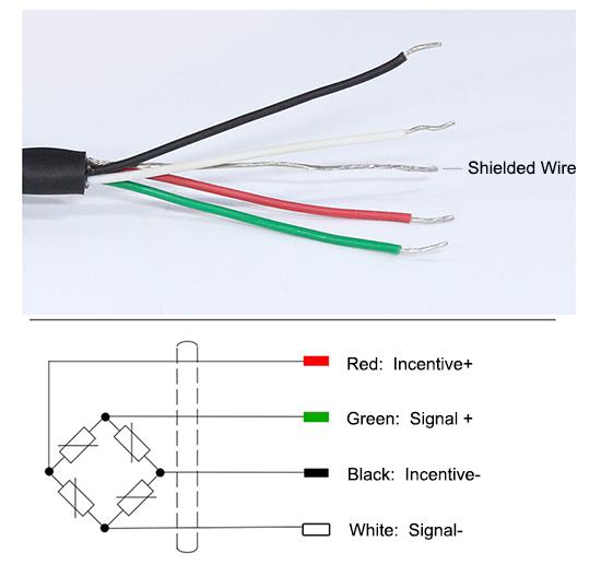
| Wiring | EXC+: Red, EXC-: Black, SIG+: Green, SIG-: White |
Reaction Torque Sensor Flange to Square Drive Dimension (unit:mm)
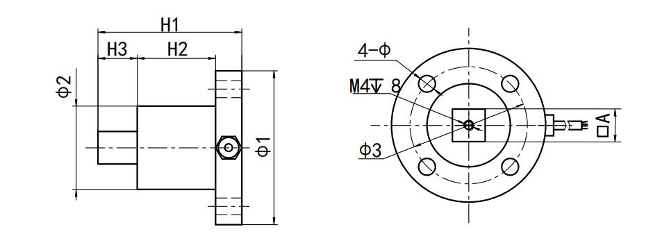
Dimension (mm)
| Capacity | A | H1 | H2 | H3 | Φ1 | Φ2 | Φ3 | Φ |
| 2-200 Nm | 12.5 | 55 | 30 | 15 | 59 | 32 | 45 | 6.5 |
| 300-800 Nm | 25.4 | 75 | 40 | 24 | 68 | 40 | 55 | 8.5 |
| 1000-2000 Nm | 25.4 | 85 | 44 | 24 | 98 | 56 | 80 | 13 |
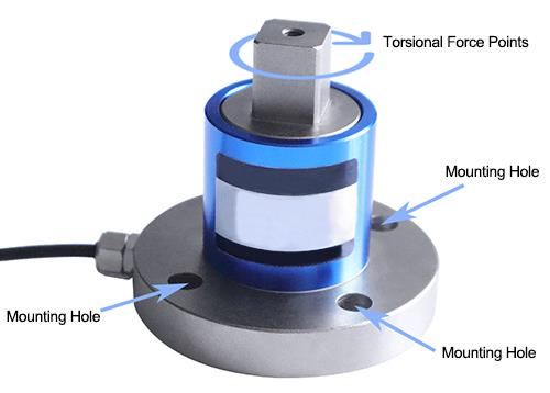
Force Diagram
Wiring Diagram
Tips: Application of torque sensor in Lift Bridge
- Vertical Lift Bridge
The mechanical rework and painting of the vertical lift bridge will probably change the weight of the mobile span. At this moment, in order to ensure the normal and safe operation in the later period, checking the balance between the span and weight is quite essential. How to check the entire balance of the balance weight cable system? A big cable can be used to connect the span with the counter weight through the pulley driven by the motor on each corner of the bridge. The torque is measured on the four drive shafts at the same time, so as to confirm if the four corners have any imbalance. Through the torque sensor and the remote telemeter connecting to each drive shaft, the torque data will be recorded in lifting and lowering the span. Through comparing the lifting torque and lowering torque, and correcting the friction, it can be proved that the movable span is slightly heavier than the combined counter weight (required condition), and all four corners are in the acceptable balance scope. - Two-leaf open bridge
The Park Street Bridge in Alameda County, California is a four-lane, two-leaf open bridge spanning 372 feet. It is located between City of Alameda and Oakland.
When the rework structure changes the weight of the original elevator, the engineers of Alameda County need to determine the appropriate counterweight to prevent the elevator drive motor from overloading. By measuring the torque on the main pinion shaft used to lift the bridge, the drive load can be easily determined and optimized by adjusting the counterweight on each span. The strain gauge of the torque sensor is connected with the pinion drive shaft and two wireless torque telemetry systems are used to simultaneously transmit strain gauge signals from the two pinions as the shaft rotates.
Alameda County has many movable bridges. Because of repair or other mechanical changes, they are occasionally in need of adjustment. Using the wireless torque sensor remote equipment can quickly and accurately conduct torque and balance measurement, eliminate the suspected and potential problems of motor driver overload.
Product reviews
Accessories for reaction torque sensors
Macrae

8/23/2021 12:47 AM
If I ordered your reaction torque sensor, dual flange, will you send us its 5 pin circular connector free of charge?
Was this review helpful? (0/0)
I am looking forward to buying 4 torque sensors.
Jumaco
11/18/2021 11:17 PM
I am looking forward to buying 4 ATO torque sensors (0-5Nm), output /-5V, and looking at the user manual. On the last page, I have pin 7 (RPM ) and 8 (RPM-) to read the machine speed in RPM. Could you please tell me what the voltage levels in these pins are? How should I read these pins with my microcontroller to compute the machine speed? Thank you!
Was this review helpful? (0/0)
Does this sensor use a strain gauge as the measurement element?
Ronda
3/6/2023 1:41 AM
Thank you for your reply. So just to confirm, even if the rotation is a small amount (only a few degrees) and slow we will still be able to measure the torque? Does this sensor use a strain gauge as the measurement element?
Was this review helpful? (0/0)
Is there any chance we can get a plug-and-play amplifier/Transmitter for the two sensors?
Drak
3/27/2023 3:29 AM
We have purchased two Reaction torque sensors and a Load Cell amplifier, but this wasn't able to read the values in a preferred way either. Is there any chance we can get a plug-and-play amplifier/Transmitter for the two sensors we have that will have:
1. zero calibration at startup.
2. It shows the value of the Torque with at least 2 decimals after the comma.
3. Does not need to connect to external PLC but shows the accurate reading of the torque value on the digital display.
4. We need to measure the 1.25-1.75 Nm range with high precision.
5. Optionally if it is possible that it can hold the maximum recorded measurement.
1. zero calibration at startup.
2. It shows the value of the Torque with at least 2 decimals after the comma.
3. Does not need to connect to external PLC but shows the accurate reading of the torque value on the digital display.
4. We need to measure the 1.25-1.75 Nm range with high precision.
5. Optionally if it is possible that it can hold the maximum recorded measurement.
Was this review helpful? (0/0)
Transmitter Options
David
7/7/2023 4:46 PM
Just curious if this sensor is compatible with more than just the ATO-S-LCTR-DY610 transmitter?
I'm looking at the ATO-LCTR-OA
I'm looking at the ATO-LCTR-OA
Was this review helpful? (0/0)
A few questions regarding the torque sensor
natalia
8/28/2023 1:43 AM
I have a few additional questions regarding the reaction torque sensor.
We plan to install sensors at the end of a shaft that will experience significant side loading in addition to torsional loading.
Is the sensor's ability to measure torque robust against changing radial and axial forces?
Is there a rating on radial or axial load for the sensor survivability?
We plan to install sensors at the end of a shaft that will experience significant side loading in addition to torsional loading.
Is the sensor's ability to measure torque robust against changing radial and axial forces?
Is there a rating on radial or axial load for the sensor survivability?
Was this review helpful? (0/0)
The side load rating for sensors
vikia
8/28/2023 3:27 AM
The ideal measurement range is 50 N-m but we might size up to survive higher loads. The side loads could get as high as 1500 N.
Could you give the side load rating for sensors with measurement ranges of 50, 100, and 200 N-m? Also, will varying side loads affect the torque measurement?
Could you give the side load rating for sensors with measurement ranges of 50, 100, and 200 N-m? Also, will varying side loads affect the torque measurement?
Was this review helpful? (0/0)
Question about limits
Thomas
9/5/2023 8:34 PM
Could you also give us these limits for the 30, 20 and 10 Nm versions of this sensor ATO-TQS-DYJN-103?
Was this review helpful? (0/0)
Reaction Torque Sensor
Levis
2/5/2024 11:13 PM
Do your torque sensors require a twist to the sensor or compression? 4-20mA and I need to measure torque from 0.1Nm to 10 Nm.
Was this review helpful? (0/0)
Output units
Sams
4/7/2026 1:31 AM
We would like to be able to directly read the output torque (in NM). Could you please provide the corresponding attachments? Additionally, could you please provide a calibration certificate sample (applicable to any of your models) so we can understand the product performance?
Was this review helpful? (0/0)
Only registered users can write reviews
Customers who bought this item also bought

Load Cell Transmitter, Output 0-5V/0-10V/4-20mA
ATO-LCTR-OA
$81.27
Load cell transmitter is made of aluminum alloy, output standard signal 0-5V/0-10V/4-20mA, has linear compensation, humidity compensation, external zero debugging, external span debugging, input overload protection and output short circuit protection functions.

Digital Load Cell Amplifier, Output 4-20mA/0-10V/RS485
ATO-LCTR-OAR
$109.85
High precision load cell amplifier has a 6 digit LED display, output signal 4-20mA/ 0-5V/ 0-10V/ RS485. There are 3 keys for parameter settings. Digital load cell amplifier can be calibrated on-line by its 3 keys. The setting parameters include zero, capacity, communication rate, division value, decimal digits, etc.

Digital Panel Meter for Displacement Sensor 4 Digit
ATO-DPM-DS4D
$174.62
Single channel digital panel meter cooperate with all kinds of analog output sensor and transmitter, realize measurement, conversion, display, transmitting, record and control, zero clearing at any time.

Tension/Compression Load Cell, Low Profile, 500kg/30 ton to 100 ton
ATO-LC-P02
$145.28
Low profile load cell also known as pancake load cell, has flat design, high strength and good symmetry. Tension and compression load cell can be applied for platform scale, truck scale, rail weighbridge and material level measurement and control in warehouse, with good anti-eccentric load performance, low height, all sealed structure and complete specifications.

Tension and Compression Load Cell, 1 kg - 500 kg
ATO-LC-TC01
$137.98
Tension and compression load cell can bear both tension and pressure, with good anti-eccentric load performance, low height, all sealed structure and complete specifications. Miniature load cell with optional capacity 1 kg/ 100kg/ 200 kg/ 300kg/ 500 kg is suited to use in restricted spaces, such as using in vehicle/test instrument/laminator measurement and control.
Related products

Reaction Torque Sensor, Dual Flange, 20 Nm/100 Nm/5000 Nm to 10000 Nm
ATO-TQS-S01
$193.92
Torque sensor is a strain gauge sensor for static torque measurement. Static torque sensor has double-flange, a 5 pin male plug and no mounting base so it can be easy to install. Reaction torque sensors have a capacity range from 20 Nm/300 Nm/2000 Nm to 10000 Nm and can measure both forward and reverse torque.

Micro Reaction Torque Sensor for Static Torque, 0.5-150 Nm
ATO-TQS-S04
$175.93
Micro torque sensor is a reaction torque sensor for static torque measurement. Torque sensor is made of aluminium alloy, 150%FS safety overload, -20°C~+80°C operating temperature, low price. Reaction torque transducers have a capacity range from 0.5 Nm ~ 150 Nm and can measure both forward and reverse torque.

Rotary Torque Sensor, Non-Contact, Shaft to Shaft, 0.05-300000 Nm
ATO-TQS-D01
$1,015.34
Rotary torque sensor is a non-contact torque sensor with two shafts and shaft keys, a male plug and a mounting base. Shaft torque sensors have a capacity range from 10 Nm/50 Nm/2000 Nm/10000 Nm to 300000 Nm. It can be applied to torque/rotary speed/power measurement of AC/DC motor, gear motor and diesel generator for a long-term.

Micro Rotary Torque Sensor for Dynamic Torque Measurement, 0.1-5 Nm
ATO-TQS-D02
$914.02
Rotary torque sensor is a strain gauge sensor for dynamic micro torque measurement. It has two shafts, a 5 pin male plug and no mounting base. Micro torque sensors have a capacity range from 0.1 Nm/0.2 Nm/0.3 Nm/0.5 Nm/1 Nm/3 Nm to 5 Nm. Rotary torque transducer can measure both forward and reverse torque.