
Gear flow meter used for continuous or intermittent measurement and control of liquid flow in pipelines for sale. The whole machine is made of stainless steel 304, optional diameter DN2-DN25, signal output optional 4-20mA/RS485/pulse output, with a wide range, high accuracy, small pressure loss, viscosity adaptability and other advantages. Applicable to petroleum, chemical, chemical fiber, transportation, trade, food, medicine and health and other departments of the flow measurement.
Specification
| Model | ATO-LW |
| Nominal Diameter | DN2-DN32 |
| Medium | Particle-free liquids, high viscosity liquids |
| Explosion-proof Grade | Exia ICT5, d IIBT4/IP67 |
| Working Pressure | 1.6MPa |
| Output Signal | Pulse, 4-20mA and RS485 communication (optional) |
| Precision Class | 0.5% |
| Casing Material | 304 stainless steel |
| Catch Material | 304 stainless steel |
| Shaft Material | Carbide |
| Transmission Material | peek, PTFE, 304 stainless steel (lining according to the medium you are measuring) |
| Power Supply | DC24V |
| Display | Liquid crystal display (instantaneous flow + totalized flow) |
| Process Connection | Threaded connection, flange (optional) |
| Working Temperature | -20°C~80°C |
| Net Weight | 1~15kg |
Flow Meter Flow Range
| Nominal Diameter | Measuring Range | Maximum Pressure | Temperature | Interface |
| DN2 | 3-50L/H | 63 Bar | -20~60℃ | G1/4 |
| DN4 | 5-250L/H | G3/8 | ||
| DN6 | 10-500L/H | G1/2 | ||
| DN10 | 50-1200L/H | G1/2 | ||
| DN15 | 200-3000L/H | G3/4 | ||
| DN25 | 1000-12000L/H | G1 |
Dimension (unit: mm)
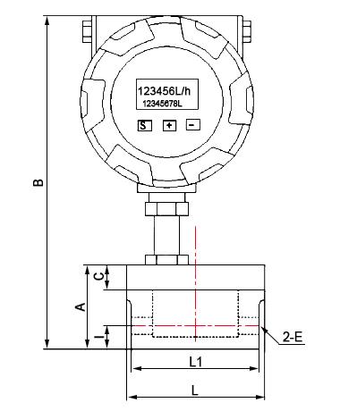
| Model | L | L1 | B | A | I | C | E |
| LW-02 | Ø83 | 77 | 210 | 53 | 13.5 | 15 | G1/4 |
| LW-04 | Ø83 | 77 | 210 | 53 | 14 | 15 | G3/8 |
| LW-06 | Ø83 | 77 | 216 | 59 | 15.6 | 15 | G1/2 |
| LW-10 | Ø83 | 77 | 216 | 59 | 15.6 | 15 | G1/2 |
| LW-15 | Ø113 | 110 | 280 | 75 | 20 | 15 | G3/4 |
| LW-25 | Ø158 | 140 | 340 | 90 | 40 | 15 | G1 |
Display Details
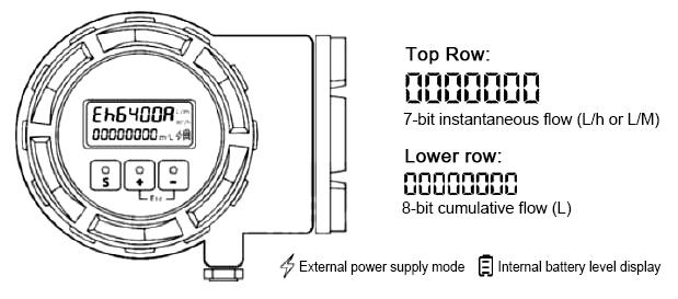
- Press button [S] to switch between total totalization and single totalization
- The display unit L is the total accumulated liters
- The unit display {blank} is for single totalization, default unit: mL.
- Press [S] + [-] to switch the unit of instantaneous volume to mL/h or L/h or mL/m.
- Use the magnet to cross over the magnetic induction area to switch the display of the meter content (e.g. total totalization, single totalization).
Working Principle
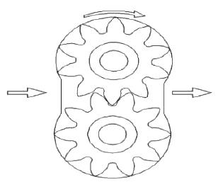
The rotational speed of the circular gear flow meter is detected by means of a sensing coil in a signal amplifier mounted on the case, which is not in contact with the measured medium.
When the transmitter gear cuts the magnetic lines of force generated by the permanent magnets in the housing, this causes a change in the magnetic flux in the sensing coil.
The sensing coil will detect the flux cycle change signal into the preamplifier, the signal is amplified, rectified, and flow rate is proportional to the pulse signal, sent to the unit conversion and flow accumulation circuit to get and display the cumulative flow value, but also the pulse signal into the frequency and current conversion circuit, the pulse signal into analog electric flow, which indicates the instantaneous flow value.
Application

Tips: Gear flow meter installation requirements
- Liquid flow meter site installation location should be avoided as far as possible, temperature, mechanical vibration, magnetic field interference, corrosive environment, should be easy to choose the location of maintenance and repair installation.
- Gear flow meter should generally be installed horizontally, the sensor must be firmly mounted on the assembly with screws. If it must be installed vertically, the liquid direction must be upward. The liquid should be full of piping, there shall be no air bubbles.
- Transmitter types of accessories in the installation, the base centerline should be aligned with the pipeline centerline, the connection of the gasket must not protrude into the liquid.
- When it is necessary to install a flow regulating valve, it must be installed on the downstream side of the sensor.
- When installing the stainless steel flow meter on the new pipeline, in order to avoid impurities in the pipeline into the transmitter, it is recommended to install a filter upstream of the transmitter.
- In order not to affect the normal transmission of liquid during maintenance, a bypass line should be installed at the installation of the transmitter.
- Magnetic fields and similar sources of interference in the vicinity of the gear flow transmitter may affect the signal picked up by the sensor. The connection between the transmitter and the display meter should be made with a shielded cable with metal, and the shield of the transmission cable should be grounded at one point at the display meter end.

Liquid Turbine Flow Meter for Water/Oil, DN4-DN200

Magnetic Water Flow Meter, Split Type PTFE Lining, DN15-DN1000

Portable Ultrasonic Flow Meter for Water, Clamp-On
