
10 hp (7.5 kW) VFD, single phase 220V, 230V, 240V to three phase output variable frequency drive. 32 amps, RS485 enabled.
Specification:
| Basics | Model | GK3000-2S0075G |
| Capacity | 10 hp (7.5 kW) | |
| Shipping weight | 8 kg | |
| Dimension | 330*200*200 mm | |
| I/O Feature | Rated current | 32 A |
| Input voltage | 1 phase 220~240V AC | |
| Input frequency | 50Hz/ 60Hz | |
| Output voltage | 3 phase AC 0~input voltage | |
| Output frequency | 0Hz~1000Hz | |
| Over load capacity | 150% of rated current for 1 minute, 180% of rated current for 3 seconds | |
| Control Feature | Control mode | V/F, Sensorless vector control (SVC), Speed sensor vector control (FVC) |
| Communication | RS485 | |
| Speed regulation | 1:100 | |
| Start torque | 150% of rating torque at 1 Hz | |
| Speed control accuracy | ≤±0.5% of rating synchronous speed | |
| Frequency precision | Digital setting: max frequency x± 0.01%; Analog setting: max frequency x± 0.2% | |
| Frequency resolution | Analog setting: 0.1% of max frequency; Digital setting: 0.01Hz | |
| Torque boost | Automatic torque boost, manual torque boost 0.1%~30.0% | |
| Interior PID controller | Be convenient to make closed-loop system | |
| Automatic energy save running | Optimize V/F curve automatically based on the load to realize power save running | |
| Automatic voltage regulation (AVR) | Can keep constant output voltage when power source voltage varies. | |
| Automatic current limiting | Limit running current automatically to avoid frequent over-current which will cause trip | |
| Environment | Enclosure rating | IP 20 |
| Temperature | –10℃~ +40℃; VFD will be derated if ambient temperature exceed 40℃; each rise 1℃, the derate will be 5% | |
| Humidity | 5%-95%, without condensation | |
| Altitude | ≤1000m; VFD will be derated if above 1000m | |
| Impingement and oscillation | Normal running:<5.9m/s2 (0.6g); Transportation:<15m/s2 (1.5g) | |
| Store environment | –20℃~ +60℃; no dust, no corrosive gas, no direct sunlight |
Note: ATO VFD Cannot be used as a power source, it Can only be directly connected to an induction motor to control the motor speed.
Details
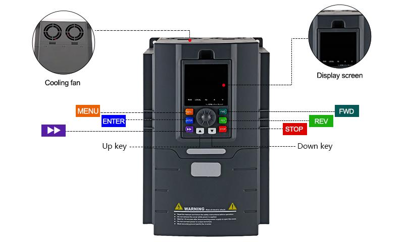
Tips: Where VFD should be placed?
Most of the users installed variable frequency drive (VFD) near the MCC because it's easy to maintain the system but there are some issue's which may happen due to placing the VFD near the MCC like there is a kind voltage reflection issue if the length of the cable is more than the critical length which may damage the motor.
In this case we need to follow instructions given in the user's manual supplied with the variable frequency drive. Generally following are recommended by manufacture:
- Maximum surrounding air (Preferred);
- Ambient temperature typically -10 C to 40 C or 50 C (Check the manual for actual);
- Mounting clearances (This is related with derating of VFD).

Today the VFD was working fine and when I changed some options I completely lost control of the device. Now the unit says I have 220V on the DC bus when I have 600V and I can't even turn the pump on.
Would like to ask you if you have the complete manual to try to configure the unit again, the printed manual we got with the unit does not describe all the options that can be configured.
Thank you in advance.
We ordered the ones that ATO had recommended and are asking me to help program them but not sure what settings are needed. I've looked at some of your videos. I thought there would be one on this page but no luck. https://www.ato.com/single-phase-to-three-phase-vfd
All the items we would be powering are motors but would the 10HP VFD work OK on a smaller motor, say a 3HP?
I'll ask for the pictures of the nameplates but should be the part numbers mentioned above.
I am controlling the frequency using analog voltage input (P0.01 = 5) and controlling the start/stop using the front panel buttons (STOP and FWD).
We have been operating this way for nearly a year now without issue.
However, a new need has arisen where I would also like to run the VFD the same way (analog control), but in reverse by pressing the REV button.
By factory default, I found P3.46 set to 030, which didn’t make sense, in the manual it shows as either 0 or 1.
When P3.46 = 030, the REV button on the front panel caused the system to jog in the forward direction.
I would like the REV button to cause the motor to spin in reverse.
Thank you for your input on this.
Is this drive ok for 208v? It seems like they are ok for 208v/230v/240v from what I read.
Can the Output voltage be adjusted? Is so, how?
Our main issue is we are getting a E-12 error. Our 3 ph power is going to (2) A/C 10 Ton condenser. These condensers will only accept 208v - 230v power /- 10%. The output of 260v put us over. We added a step down transformer from 240v - 208v and now the power output is 214v, but the E-12 error is still occurring.
Thoughts? I would be very beneficial to speak to you direct.

7.5 hp VFD, Single Phase to Three Phase VFD

15 hp VFD, Single Phase to Three Phase VFD

5 hp VFD, Single Phase to Three Phase VFD

20 hp VFD, Single Phase to Three Phase VFD

Diaphragm Pressure Sensor for Water/Viscous Liquid
7.5 hp VFD, Single Phase to Three Phase VFD
5 hp VFD, Single Phase to Three Phase VFD

3 hp VFD, Single Phase to Three Phase VFD
