Waterproof Limit Switch, 1NO 1NC, 3A/250VAC, 5A/125VAC

$89.95
Waterproof limit switch adopts fully sealed structure, can be used in the industrial occasions required for oil-resistant, waterproof and dustproof. There are different types of actuator for waterproof limit switch, such as roller plunger, roller lever, top plunger and coil spring. It contains two contact switches 1NO+ 1NC and can be used in the environment temperature -25~+70℃ (-13~+158℉). Waterproof limit switches apply to AC-15, 5A/250VAC, 3A/125VAC. Other rated current/voltage is customizable, such as 0.4A/125VDC, 0.2A/250VDC, etc.
SKU: ATO-WPLS
*
Free Shipping
Delivery date: 6-12 days

Waterproof limit switch with contact type 1NO + 1NC has different types of actuator, such as roller plunger, roller lever, top plunger and coil spring. It applies to AC-15, 5A/250VAC, 3A/125VAC. Other rated current/voltage can be customizable. The limit switch has an IP67 protection level and strong protection capability and can be used in a variety of industrial environments.

Specification

ModelATO-WPLS
Weight360~540g
Rated current/voltageAC-15, 3A/250VAC, 5A/125VAC (Customizable rated voltage is shown in the reference table below.)
Contact type1NO+1NC
WiringBlack: (+) COM; Blue: NO; Red: NC; Green: E
Cable length3m
Operating speed1mm/s~1m/s
Operating frequencyMachinery: 120 times/minute
Electric: 30 times/minute
Contact resistance<15MΩ, initial stage
Insulation resistance>100MΩ (<500VDC)
Withstand voltageBetween no-connection terminals: 1000VAC, 50/60Hz lasts 1 minute
Between the terminal and the contact: 1500VAC, 50/60Hz lasts 1 minute
Between terminal and no-load current metal: 1500VAC, 50/60Hz lasts 1 minute
VibrationMisoperation endurance: 10~55Hz, 1.5mm, double-amplitude
ImpactMechanical endurance: >1000m/s2 (>100G)
Misoperation endurance: >500m/s2 (>30G)
Shell materialCast aluminum alloy
Temperature-25~+70℃ (-13~+158℉)
Humidity<95%RH
Working lifeMachinery: >1million times
Electric: >0.2million times
Protection classIP67


Operating characteristic

ModelATO-WPLS-4203ATO-WPLS-4204ATO-WPLS-4213ATO-WPLS-4214
ActuatorRoller plungerRoller plungerRoller plungerRoller plunger
OF Max.1200gf (11.77N)1200gf (11.77N)1800gf (17.56N)1800gf (17.56N)
RF Min.450gf (4.41N)450gf (4.41N)450gf (4.41N)450gf (4.41N)
PT Max.1.8mm1.8mm1.8mm1.8mm
OT Min.3mm3mm3mm3mm
MD Max.0.2mm0.2mm0.2mm0.2mm
OP28.5±1mm28.5±1mm34.3±1mm34.3±1mm
ModelATO-WPLS-4205ATO-WPLS-4209ATO-WPLS-4212ATO-WPLS-4270
ActuatorRoller leverAdjustable roller leverTop plungerCoil spring
OF Max.580gf (5.69N)580gf (5.69N)1800gf (17.56N)150gf (1.47N)
RF Min.150gf (1.47N)150gf (1.47N)450gf (4.41N)-
PT Max.25°25°1.8mm15°
OT Min.40°40°3mm-
MD Max.3°3°0.2mm-
OP--24.9±1mm-

Explanation of parameters:
OF means operating force, the force that must be applied to the drive rod in order to move from the free position to the operation position.
RF means release force, the force that must be applied to the drive rod in order to move from the total travel position to the return position.
PT means pretravel, the distance the drive rod moves from the free position to the operation position.
OT means overtravel, the moving distance or moving angle of the drive rod from the operation position to the full stroke position.
MD means movement differential, the moving distance or moving angle of the drive rod from the operation position to the return position.
OP means operating position, at which the external force is applied to the drive lever to make the movable contact just operating from the state of the free position.

Reference table for customizable rated voltage and rated current

Rated voltageRated current (A)
Non-inductive loadInductive load
Resistive loadLamp loadInductive loadMotor load
NCNONCNONCNONCNO
125VAC5 (0.1)1.50.732.51.3
250VAC310.521.50.8
8VDC5 (0.1)2543
14VDC5 (0.1)2443
30VDC4 (0.1)2333
125VDC0.40.050.40.05
250VDC0.20.030.20.03

Note:

  1. Power factor of inductive load is above 0.4 (AC). The time constant is below 7ms (DC).
  2. The inrush current of lamp load is 10 times that of steady state current, and the inrush current of motor load is 6 times that of steady state current.

Dimension (unit: mm)

1. Waterproof limit switch with roller plunger dimensional drawing:
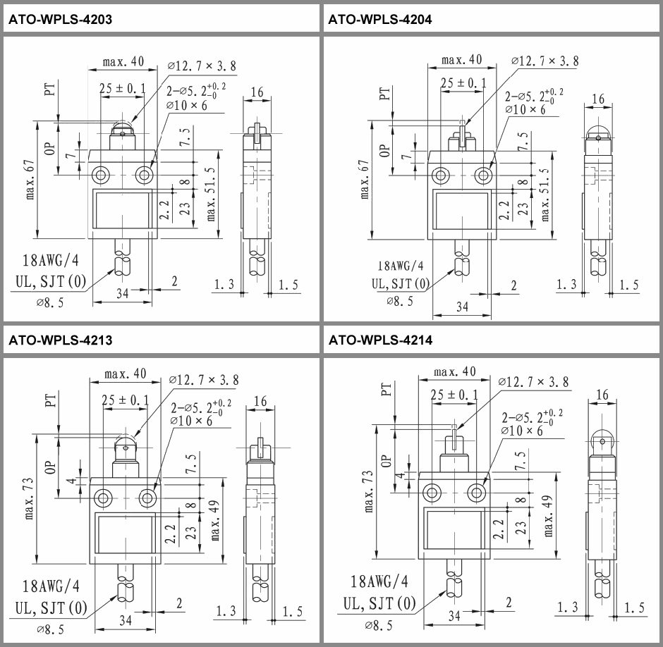
Waterproof limit switch with roller plunger dimensional drawing

2. Waterproof limit switch with roller lever/top plunger/coil spring dimensional drawing:
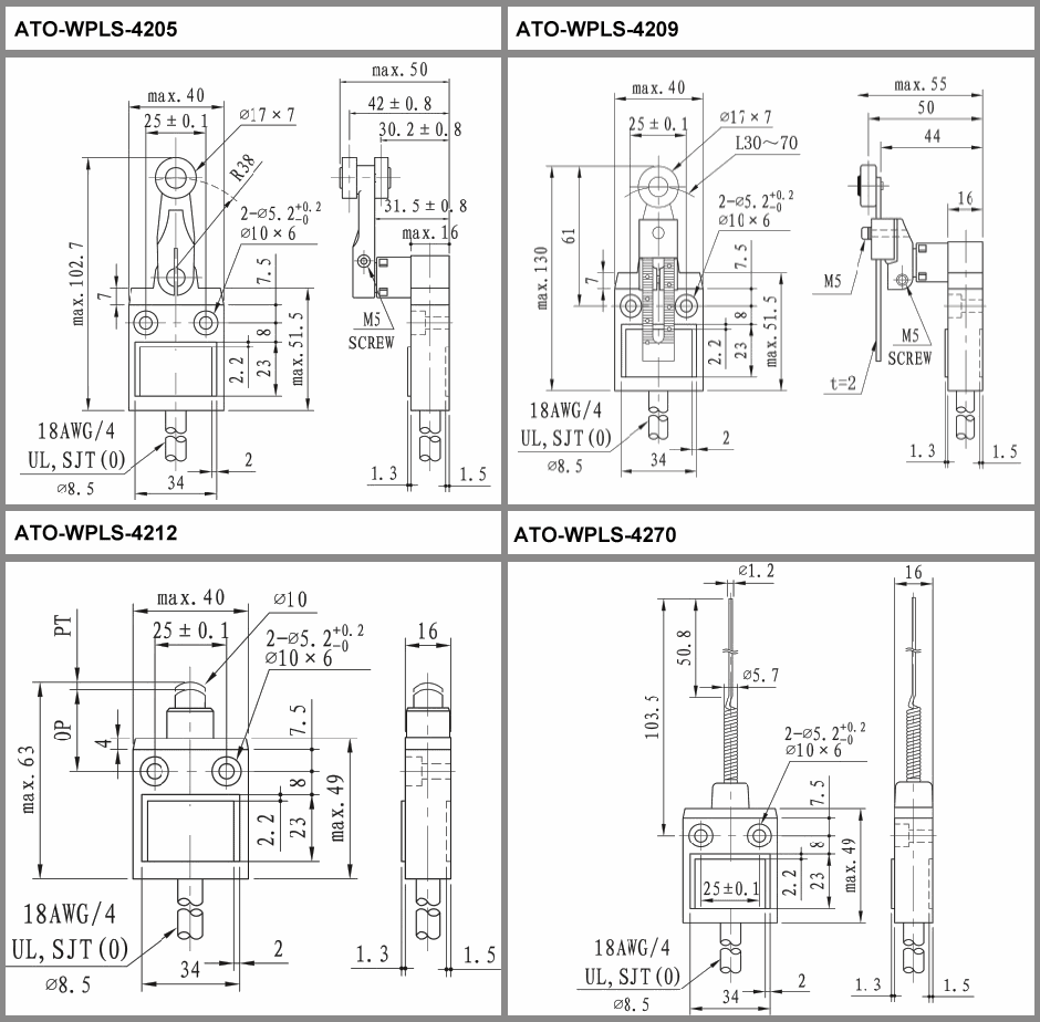
Waterproof limit switch with roller lever/top plunger/coil spring dimensional drawing

Tips: 12 points to note for limit switch operation

  1. In order to prevent the actuator of the limit switch from a sudden return or being impacted, considering using the operating object (cam, stopper, etc.) for operation. When operating the limit switch with relatively fast action, it is necessary to use cams and stoppers that adequately energize relays and valves and maintain long strokes.
  2. Operation method, cam and stopper shape, frequency and over-travel can greatly affect the life and accuracy. Therefore, please design the cam and the stopper to be smooth shape.
  3. A normal load must also be applied to the actuator of the limit switch during rotary motion and linear motion. If the stopper touches the support rod, the action position will not be stable.
  4. Please do not apply eccentric load to the actuator of the switch, or cause local friction.
  5. If a load is applied to the actuator (roller) of the limit switch from an inclined direction, the actuator may be deformed or damaged, so keep the stopper perpendicular to the actuator.
  6. Please set the actuator not to exceed the overtravel (OT). If the overtravel (OT) exceeds the limit, it may cause a malfunction. When installing, make adjustments after taking into account the total operating stroke.
  7. When the overtravel (OT) is too large, early failures may be induced. Therefore, it must be adjusted during installation, and the process of the operating object must be thoroughly discussed in advance.
  8. For the acicular plunger type limit switch, the plunger stroke and the operating object stroke must be on a vertical line.
  9. Please use the waterproof limit switch according to the characteristics of the actuator.
  10. Please do not process the actuator to cause the movement position to change.
  11. When using a long side rod such as an adjustable lever, it may cause a swaying state, and the following measures are recommended:
    1. The rear end of the stopper is set to a smooth 15~30° angle, or connected with a quadratic curve.
    2. Please modify the circuit to ensure that there is no wrong action signal in the circuit.
    3. Please use a limit switch that can operate on one side (or set it as a one-sided action to use).
  12. For the bevel plunger type limit switch, use a limit switch whose plunger width is less than the operating object width.

VFD Emergency Stop with Limit Switches

In this video, you will learn about the setup and operation of emergency stopping a motor by using limit switches and a variable frequency drive (VFD). By combining the limit switches of the emergency stop function with the VFD GK3000, a strong safety measure can be established that can quickly stop the motor operation in an emergency.

Automatic Material Trolley Control with Limit Switch

In this video, the method of applying limit switches to automatic material trolley control is demonstrated.

Roller Limit Switch NO NC Contact Wiring and Detection

In this video, the roller limit switch NO NC contact wiring and detection operation are shown.

Product reviews
Best waterproof limit switch
5
Peter
Avatar
3/23/2022 11:58 PM
I used four of these water limit switches for my son. Absolutely perfect. I have nothing to complain. The previous limit switches last two weeks before they failed. I wish I would have bought these first.
Was this review helpful? Yes No (0/0)
Well built limit switch
5
Alob
Avatar
6/15/2022 7:06 PM
I've been using this limit switch for months and it works perfectly. Using this limit switch can protect my motor well. Also, it's waterproof. I would recommend it to my friends.
Was this review helpful? Yes No (0/0)
Write your review
  • Only registered users can write reviews
*
*
  • Bad
  • Excellent
*
*
*
*

Waterproof limit switch with contact type 1NO + 1NC has different types of actuator, such as roller plunger, roller lever, top plunger and coil spring. It applies to AC-15, 5A/250VAC, 3A/125VAC. Other rated current/voltage can be customizable. The limit switch has an IP67 protection level and strong protection capability and can be used in a variety of industrial environments.

Specification

ModelATO-WPLS
Weight360~540g
Rated current/voltageAC-15, 3A/250VAC, 5A/125VAC (Customizable rated voltage is shown in the reference table below.)
Contact type1NO+1NC
WiringBlack: (+) COM; Blue: NO; Red: NC; Green: E
Cable length3m
Operating speed1mm/s~1m/s
Operating frequencyMachinery: 120 times/minute
Electric: 30 times/minute
Contact resistance<15MΩ, initial stage
Insulation resistance>100MΩ (<500VDC)
Withstand voltageBetween no-connection terminals: 1000VAC, 50/60Hz lasts 1 minute
Between the terminal and the contact: 1500VAC, 50/60Hz lasts 1 minute
Between terminal and no-load current metal: 1500VAC, 50/60Hz lasts 1 minute
VibrationMisoperation endurance: 10~55Hz, 1.5mm, double-amplitude
ImpactMechanical endurance: >1000m/s2 (>100G)
Misoperation endurance: >500m/s2 (>30G)
Shell materialCast aluminum alloy
Temperature-25~+70℃ (-13~+158℉)
Humidity<95%RH
Working lifeMachinery: >1million times
Electric: >0.2million times
Protection classIP67


Operating characteristic

ModelATO-WPLS-4203ATO-WPLS-4204ATO-WPLS-4213ATO-WPLS-4214
ActuatorRoller plungerRoller plungerRoller plungerRoller plunger
OF Max.1200gf (11.77N)1200gf (11.77N)1800gf (17.56N)1800gf (17.56N)
RF Min.450gf (4.41N)450gf (4.41N)450gf (4.41N)450gf (4.41N)
PT Max.1.8mm1.8mm1.8mm1.8mm
OT Min.3mm3mm3mm3mm
MD Max.0.2mm0.2mm0.2mm0.2mm
OP28.5±1mm28.5±1mm34.3±1mm34.3±1mm
ModelATO-WPLS-4205ATO-WPLS-4209ATO-WPLS-4212ATO-WPLS-4270
ActuatorRoller leverAdjustable roller leverTop plungerCoil spring
OF Max.580gf (5.69N)580gf (5.69N)1800gf (17.56N)150gf (1.47N)
RF Min.150gf (1.47N)150gf (1.47N)450gf (4.41N)-
PT Max.25°25°1.8mm15°
OT Min.40°40°3mm-
MD Max.3°3°0.2mm-
OP--24.9±1mm-

Explanation of parameters:
OF means operating force, the force that must be applied to the drive rod in order to move from the free position to the operation position.
RF means release force, the force that must be applied to the drive rod in order to move from the total travel position to the return position.
PT means pretravel, the distance the drive rod moves from the free position to the operation position.
OT means overtravel, the moving distance or moving angle of the drive rod from the operation position to the full stroke position.
MD means movement differential, the moving distance or moving angle of the drive rod from the operation position to the return position.
OP means operating position, at which the external force is applied to the drive lever to make the movable contact just operating from the state of the free position.

Reference table for customizable rated voltage and rated current

Rated voltageRated current (A)
Non-inductive loadInductive load
Resistive loadLamp loadInductive loadMotor load
NCNONCNONCNONCNO
125VAC5 (0.1)1.50.732.51.3
250VAC310.521.50.8
8VDC5 (0.1)2543
14VDC5 (0.1)2443
30VDC4 (0.1)2333
125VDC0.40.050.40.05
250VDC0.20.030.20.03

Note:

  1. Power factor of inductive load is above 0.4 (AC). The time constant is below 7ms (DC).
  2. The inrush current of lamp load is 10 times that of steady state current, and the inrush current of motor load is 6 times that of steady state current.

Dimension (unit: mm)

1. Waterproof limit switch with roller plunger dimensional drawing:

Waterproof limit switch with roller plunger dimensional drawing

2. Waterproof limit switch with roller lever/top plunger/coil spring dimensional drawing:

Waterproof limit switch with roller lever/top plunger/coil spring dimensional drawing

Tips: 12 points to note for limit switch operation

  1. In order to prevent the actuator of the limit switch from a sudden return or being impacted, considering using the operating object (cam, stopper, etc.) for operation. When operating the limit switch with relatively fast action, it is necessary to use cams and stoppers that adequately energize relays and valves and maintain long strokes.
  2. Operation method, cam and stopper shape, frequency and over-travel can greatly affect the life and accuracy. Therefore, please design the cam and the stopper to be smooth shape.
  3. A normal load must also be applied to the actuator of the limit switch during rotary motion and linear motion. If the stopper touches the support rod, the action position will not be stable.
  4. Please do not apply eccentric load to the actuator of the switch, or cause local friction.
  5. If a load is applied to the actuator (roller) of the limit switch from an inclined direction, the actuator may be deformed or damaged, so keep the stopper perpendicular to the actuator.
  6. Please set the actuator not to exceed the overtravel (OT). If the overtravel (OT) exceeds the limit, it may cause a malfunction. When installing, make adjustments after taking into account the total operating stroke.
  7. When the overtravel (OT) is too large, early failures may be induced. Therefore, it must be adjusted during installation, and the process of the operating object must be thoroughly discussed in advance.
  8. For the acicular plunger type limit switch, the plunger stroke and the operating object stroke must be on a vertical line.
  9. Please use the waterproof limit switch according to the characteristics of the actuator.
  10. Please do not process the actuator to cause the movement position to change.
  11. When using a long side rod such as an adjustable lever, it may cause a swaying state, and the following measures are recommended:
    1. The rear end of the stopper is set to a smooth 15~30° angle, or connected with a quadratic curve.
    2. Please modify the circuit to ensure that there is no wrong action signal in the circuit.
    3. Please use a limit switch that can operate on one side (or set it as a one-sided action to use).
  12. For the bevel plunger type limit switch, use a limit switch whose plunger width is less than the operating object width.
Product reviews
Best waterproof limit switch
5
Peter
Avatar
3/23/2022 11:58 PM
I used four of these water limit switches for my son. Absolutely perfect. I have nothing to complain. The previous limit switches last two weeks before they failed. I wish I would have bought these first.
Was this review helpful? Yes No (0/0)
Well built limit switch
5
Alob
Avatar
6/15/2022 7:06 PM
I've been using this limit switch for months and it works perfectly. Using this limit switch can protect my motor well. Also, it's waterproof. I would recommend it to my friends.
Was this review helpful? Yes No (0/0)
Only registered users can write reviews