Thermocouple, J type, Assembly

$59.96
J type thermocouple assembles with protection head and stainless steel thermowell. Its thermo wire diameter is Ф2.5mm. J type thermocouple can directly measure the temperature of liquid, vapor, gas medium and solid surface in the range of 0~500 ℃ in various production processes, especially in vacuum, oxidation, reduction or inert atmosphere.
SKU: ATO-TC-JA
*
This product has a minimum quantity of 2
Free Shipping
Delivery date: 6-12 days

As a temperature sensor, thermocouple assembly is usually used with display instruments, recording instruments and signal conditioners.

Specification

1. Thermocouple temperature range chart

CategoryType of sensing elementRelationship between wire diameter and temperature
Thermo wire diameter (mm)Long-term temperature (℃)Short-tem temperature (℃)
Platinum Rhodium 30 - Platinum Rhodium 6B typeΦ0.516001800
Platinum Rhodium 13 - PlatinumR typeΦ0.513001600
Platinum Rhodium 10 - PlatinumS typeΦ0.513001600
Nickel chromium silicon - Nickel silicon magnesiumN typeΦ0.3700800
Φ0.5800900
Φ0.8, Φ1.09001000
Φ1.2, Φ1.610001100
Φ2.0, Φ2.511001200
Φ3.212001300
Nickel chromium - Nickel siliconK typeΦ0.3700800
Φ0.5800900
Φ0.8, Φ1.09001000
Φ1.2, Φ1.610001100
Φ2.0, Φ2.511001200
Φ3.212001300
Nickel chromium - Copper nickelE typeΦ0.3350450
Φ0.5450550
Φ0.8, Φ1.0550650
Φ1.2, Φ1.6650750
Φ2.0, Φ2.5750900
Iron - ConstantanJ typeΦ0.3, Φ0.5300400
Φ0.8, Φ1.0400500
Φ1.2, Φ1.6500600
Φ2.0, Φ2.5600750
Copper - Copper nickelT typeΦ0.2150200
Φ0.3, Φ0.5200250
Φ1.0250300
Φ1.6350400

2. Thermowell application temperature range chart

Thermowell materialLong-term temperatureShort-term temperature
Corundum CT116001800
High alumina CT213001600
Nickel base wrought superalloys 3YC5213001350
Nickel base wrought superalloys GH303912501320
Nickel base superalloys GH303012001250
Heat resistant stainless steel 2Cr25Ni2012001250
Silicon carbide11001150
Stainless steel 316L900950
Stainless steel 1Cr18Ni9Ti800900

3. Thermowell installing form (unit: mm)
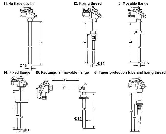
Thermocouple thermowell installing form
4. Selection chart

Total length of thermowell (L or L*L1)Branch numberThermowell installing formProtection head formDiameter and material of thermowell
300~2150mm (for I1, I2, I3, I4);
500*500mm, 750*500mm, 750*750mm (for I5);
225~450mm (for I6)
B1: Single branch;
B2: Double branch
I0: No thermowell;
I1: No fixed device;
I2: Fixing thread;
I3: Movable flange;
I4: Fixed flange;
I5: Rectangular movable flange;
I6: Taper thermowell and fixing thread
C1: No protection head;
C2: All stainless steel protection head;
C3: Waterproof protection head;
C4: Explosion-proof protection head
D0: Φ16mm;
D1: Φ25mm, double-deck;
D2: Φ16mm high quality aluminum;
D3: Φ20mm high quality aluminum

5. Thermocouple assembly installation diagram
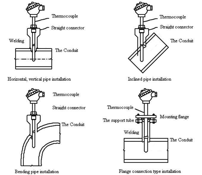
Thermocouple assembly installation diagram

Application

Thermocouple J type assembly application

Tips: Troubleshooting for thermocouple thermode
Thermode is a metal conductor. In usage, due to long-term smoking of high temperature and influence of surrounding environmental smell (corrosion, water vapor), it will be aged and deteriorate, and causes changes of the correspondence of thermal electromotive force an temperature of thermode and deviations of temperature-millivolt voltage comparison table, thus giving rise to errors of temperature measurement.
Or the insertion depth of thermode is not enough. The fault generally happens in new devices or in process of repair of devices. Length of protective casing in installation of thermocouple is not enough, which causes distance in pipeline equipment fail to reach to the center of medium and temperature measurement end of thermocouple fail to reach to the peak of temperature, thus causing the measured temperature lower. If insertion depth of thermocouple is too close to outer wall of pipeline equipment, errors will be much bigger and even losing the significance of measurement. If protective casing is long enough while thermode is not long enough, it can be disposed by finding an enough long one to insert in. If protective casing is not long enough, it cannot be disposed but change after the device stops.

Fixed Installation Dimension Drawing

Design serial number1
Structure diagramThermocouple RDT sensor dimension
NameFixed thread
SizeM27*2 (default), G3/4", M33*2, G1", other
Protection tubeDiameterφ12mm, φ16mm, other
Texture of material1Cr18Ni9Ti, 2Cr25Ni20, other
Withstand voltage≤10MPa
Design serial number2
Structure diagramThermocouple RDT sensor dimension
NameMovable flange
Protection tubeDiameterφ12mm, φ16mm, other
Texture of material1Cr18Ni9Ti, 2Cr25Ni20, other
Withstand voltageAtmospheric pressure
Design serial number3
Structure diagramThermocouple RDT sensor dimension
NameFixed flange
SizeDN15mm (default)D095mmDN20mm105mm
D165mm75mm
D245mm55mm
φn4-φ14mm4-φ14mm
DN25mmD0115mmDN32mm140mm
D185mm100mm
D265mm78mm
φn4-φ14mm4-φ18mm
DN40mmD0150mmDN50mm165mm
D1110mm125mm
D285mm100mm
φn4-φ18mm4-φ18mm
H12mm
Protection tubeDiameterφ12mm, φ16mm, other
Texture of material1Cr18Ni9Ti, 2Cr25Ni20, other
Withstand voltage≤6.4MPa
Design serial number4
Structure diagramThermocouple RDT sensor dimension
NameConical fixed thread
SizeM27*2 (default), M33*2, G1", other
Protection tubeDiameterφ12mm, φ16mm, other
Texture of material1Cr18Ni9Ti, 2Cr25Ni20, other
Withstand voltage≥30MPa
Write your review
  • Only registered users can write reviews
*
*
  • Bad
  • Excellent
*
*
*
*

As a temperature sensor, thermocouple assembly is usually used with display instruments, recording instruments and signal conditioners.

Specification

1. Thermocouple temperature range chart

CategoryType of sensing elementRelationship between wire diameter and temperature
Thermo wire diameter (mm)Long-term temperature (℃)Short-tem temperature (℃)
Platinum Rhodium 30 - Platinum Rhodium 6B typeΦ0.516001800
Platinum Rhodium 13 - PlatinumR typeΦ0.513001600
Platinum Rhodium 10 - PlatinumS typeΦ0.513001600
Nickel chromium silicon - Nickel silicon magnesiumN typeΦ0.3700800
Φ0.5800900
Φ0.8, Φ1.09001000
Φ1.2, Φ1.610001100
Φ2.0, Φ2.511001200
Φ3.212001300
Nickel chromium - Nickel siliconK typeΦ0.3700800
Φ0.5800900
Φ0.8, Φ1.09001000
Φ1.2, Φ1.610001100
Φ2.0, Φ2.511001200
Φ3.212001300
Nickel chromium - Copper nickelE typeΦ0.3350450
Φ0.5450550
Φ0.8, Φ1.0550650
Φ1.2, Φ1.6650750
Φ2.0, Φ2.5750900
Iron - ConstantanJ typeΦ0.3, Φ0.5300400
Φ0.8, Φ1.0400500
Φ1.2, Φ1.6500600
Φ2.0, Φ2.5600750
Copper - Copper nickelT typeΦ0.2150200
Φ0.3, Φ0.5200250
Φ1.0250300
Φ1.6350400

2. Thermowell application temperature range chart

Thermowell materialLong-term temperatureShort-term temperature
Corundum CT116001800
High alumina CT213001600
Nickel base wrought superalloys 3YC5213001350
Nickel base wrought superalloys GH303912501320
Nickel base superalloys GH303012001250
Heat resistant stainless steel 2Cr25Ni2012001250
Silicon carbide11001150
Stainless steel 316L900950
Stainless steel 1Cr18Ni9Ti800900

3. Thermowell installing form (unit: mm)
Thermocouple thermowell installing form
4. Selection chart

Total length of thermowell (L or L*L1)Branch numberThermowell installing formProtection head formDiameter and material of thermowell
300~2150mm (for I1, I2, I3, I4);
500*500mm, 750*500mm, 750*750mm (for I5);
225~450mm (for I6)
B1: Single branch;
B2: Double branch
I0: No thermowell;
I1: No fixed device;
I2: Fixing thread;
I3: Movable flange;
I4: Fixed flange;
I5: Rectangular movable flange;
I6: Taper thermowell and fixing thread
C1: No protection head;
C2: All stainless steel protection head;
C3: Waterproof protection head;
C4: Explosion-proof protection head
D0: Φ16mm;
D1: Φ25mm, double-deck;
D2: Φ16mm high quality aluminum;
D3: Φ20mm high quality aluminum

5. Thermocouple assembly installation diagram
Thermocouple assembly installation diagram

Application

Thermocouple J type assembly application

Tips: Troubleshooting for thermocouple thermode
Thermode is a metal conductor. In usage, due to long-term smoking of high temperature and influence of surrounding environmental smell (corrosion, water vapor), it will be aged and deteriorate, and causes changes of the correspondence of thermal electromotive force an temperature of thermode and deviations of temperature-millivolt voltage comparison table, thus giving rise to errors of temperature measurement.
Or the insertion depth of thermode is not enough. The fault generally happens in new devices or in process of repair of devices. Length of protective casing in installation of thermocouple is not enough, which causes distance in pipeline equipment fail to reach to the center of medium and temperature measurement end of thermocouple fail to reach to the peak of temperature, thus causing the measured temperature lower. If insertion depth of thermocouple is too close to outer wall of pipeline equipment, errors will be much bigger and even losing the significance of measurement. If protective casing is long enough while thermode is not long enough, it can be disposed by finding an enough long one to insert in. If protective casing is not long enough, it cannot be disposed but change after the device stops.

Only registered users can write reviews