Liquid Level Control Relay, Level Monitoring, SPDT, AC/DC 24-240V

$65.72
Liquid level control relay is a key automated liquid level monitoring component. The SPDT design of the liquid level control relay allows the relay to switch between two independent load circuits, such as pump start stop control or alarm signals, when the liquid level changes. This liquid level control relay is compatible with both AC and DC power sources, with a wide voltage range from 24V to 240V, making it suitable for most industrial power supply environments.
SKU: ATO-MR-GRL8
Free Shipping
Delivery date: 6-12 days

Liquid level control relay is a component specifically designed for automated liquid level monitoring, which achieves precise control of liquid level through SPDT switches and can operate reliably within the voltage range of 24-240V under AC and DC power sources. Designed for monitoring level in wells, basins, reservoirs, tanks. When the liquid level reaches the preset high and low threshold, it will automatically connect or disconnect the circuit, ensuring the safe operation and effective management of the equipment.

Feature

  • ln one device you can choose the following configurations: 2 level control mode or 1 level control mode.
  • Choice of function PUMP UP, PUMP DOWN.
  • Adjustable time delay on the output (0.1-10s).
  • Sensitivity adjustable by a potentiometer (5-100kΩ).
  • Galvanically separated supply voltage AC/DC 24-240V.
  • Relay status is indicated by LED.
  • 1-MODULE, DIN rail mounting.

Specification

ModelATO-GRL8-02
Function2 or 1 level control mode
Supply terminalsA1-A2
Voltage rangeAC/DC 24-240V (50-60Hz)
lnputmax.2VA
Supply voltage tolerance-15%; +10%
Sensitivity (input resistance)adjustable in range 5 kΩ-100 kΩ
Voltage in electrodesmax.AC 5V
Current in probeAC<0.1 mA
Time responsemax.400 ms
Max.capacity length800 m (sensitivity 25 kΩ), 200 m (sensitivity 100 kΩ)
Max.capacity of probe cable400 nF (sensitivity 25kΩ), 100 nF (sensitivity 100 kΩ)
Time delay (t)adjustable, 0.1-10s
Accuracy in setting (mechanical)±10 %
Temperature coefficient0.05%/℃, at=20℃ (0.05%°F, at=68°F)
Output1×SPDT
Current rating10A/AC1
Switching voltage250VAC/24VDC
Min.breaking capacity DC500mW
Output indicationred LED
Mechanical life1×107
Electrical life (AC1)1×10⁵
Reset timemax.200ms
Operating temperature-20℃ to +55°C (-4°F to 131°F)
Storage temperature-35°C to +75°C (-22°F to 158°F)
Mounting/DIN railDin rail EN/IEC 60715
Protection degreeIP40 for front panel/IP20 terminals
Operating altitude≤2000m
Operating positionany
Overvoltage cathegoryⅢ.
Pollution degree2
Max.cable size (mm2)solid wire max.1×2.5 or 2×1.5/with sleeve max.1×2.5 (AWG 12)
Dimensions90×18×64mm
Weight81g
StandardsGB/T 14048.5, EN 60255-1

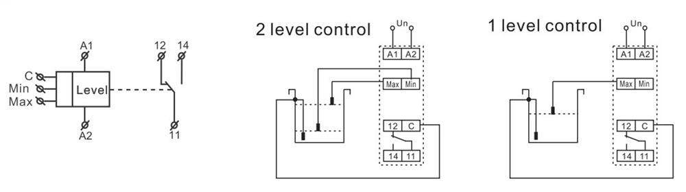
Wiring Diagram

Liquid level control relay wiring diagram

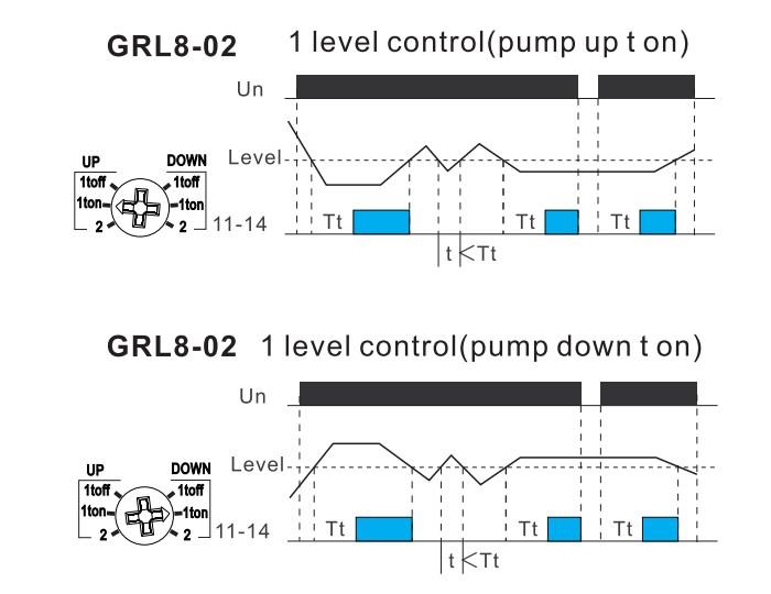
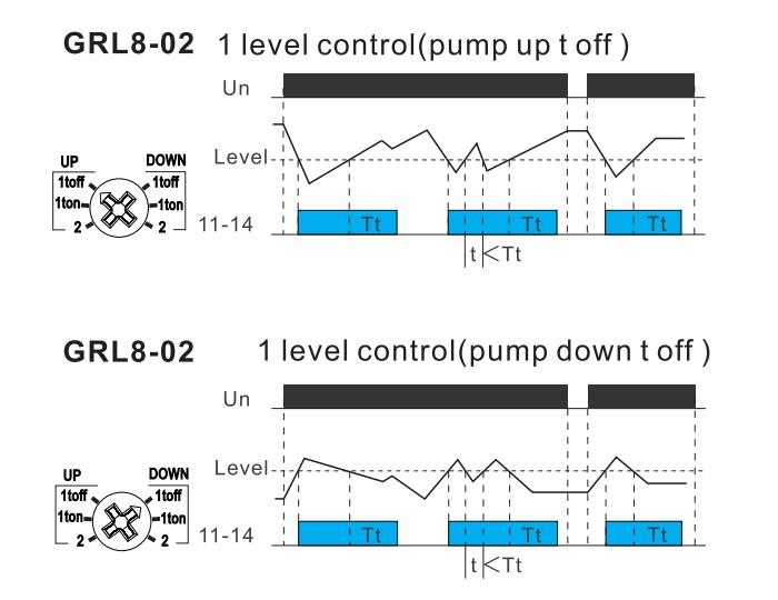
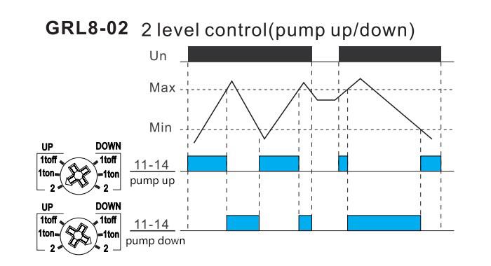
Functions Diagram

Liquid level control relay functions diagram1Liquid level control relay functions diagram2Liquid level control relay functions diagram3

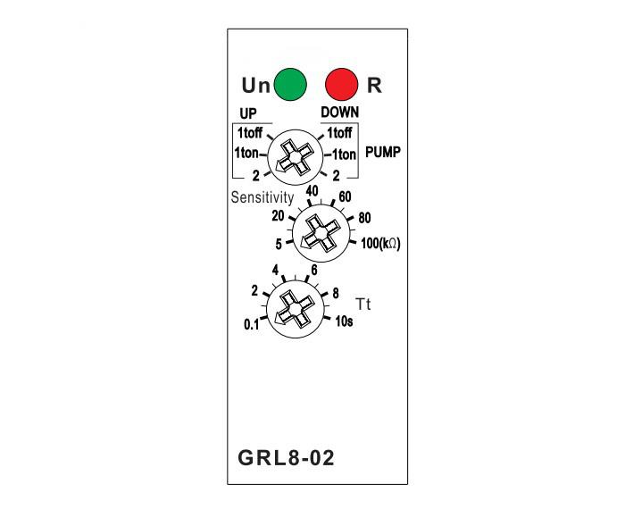
Panel Diagram

Liquid level control relay panel diagram

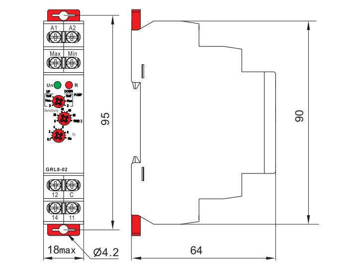
Dimensions (mm)

Liquid level control relay dimensions

Tips: Working principle of the liquid level control relay

A liquid level relay is a relay that controls the liquid level and has electronic circuits inside. Utilize the conductivity of liquids, when the liquid level reaches a certain height, the relay will act to cut off the power supply. Turn on the power to start the water pump when the liquid level is below a certain level. Achieve the function of automatic control. Automatic control consists of sensors and control actuators. The sensor of the liquid level controller is usually a wire. Utilize the conductivity of water. Water has poor conductivity and cannot directly drive relays. So electronic circuits need to amplify the current to drive the relay to work.

Write your review
  • Only registered users can write reviews
*
*
  • Bad
  • Excellent
*
*
*
*

Liquid level control relay is a component specifically designed for automated liquid level monitoring, which achieves precise control of liquid level through SPDT switches and can operate reliably within the voltage range of 24-240V under AC and DC power sources. Designed for monitoring level in wells, basins, reservoirs, tanks. When the liquid level reaches the preset high and low threshold, it will automatically connect or disconnect the circuit, ensuring the safe operation and effective management of the equipment.

Feature

  • ln one device you can choose the following configurations: 2 level control mode or 1 level control mode.
  • Choice of function PUMP UP, PUMP DOWN.
  • Adjustable time delay on the output (0.1-10s).
  • Sensitivity adjustable by a potentiometer (5-100kΩ).
  • Galvanically separated supply voltage AC/DC 24-240V.
  • Relay status is indicated by LED.
  • 1-MODULE, DIN rail mounting.

Specification

ModelATO-GRL8-02
Function2 or 1 level control mode
Supply terminalsA1-A2
Voltage rangeAC/DC 24-240V (50-60Hz)
lnputmax.2VA
Supply voltage tolerance-15%; +10%
Sensitivity (input resistance)adjustable in range 5 kΩ-100 kΩ
Voltage in electrodesmax.AC 5V
Current in probeAC<0.1 mA
Time responsemax.400 ms
Max.capacity length800 m (sensitivity 25 kΩ), 200 m (sensitivity 100 kΩ)
Max.capacity of probe cable400 nF (sensitivity 25kΩ), 100 nF (sensitivity 100 kΩ)
Time delay (t)adjustable, 0.1-10s
Accuracy in setting (mechanical)±10 %
Temperature coefficient0.05%/℃, at=20℃ (0.05%°F, at=68°F)
Output1×SPDT
Current rating10A/AC1
Switching voltage250VAC/24VDC
Min.breaking capacity DC500mW
Output indicationred LED
Mechanical life1×107
Electrical life (AC1)1×10⁵
Reset timemax.200ms
Operating temperature-20℃ to +55°C (-4°F to 131°F)
Storage temperature-35°C to +75°C (-22°F to 158°F)
Mounting/DIN railDin rail EN/IEC 60715
Protection degreeIP40 for front panel/IP20 terminals
Operating altitude≤2000m
Operating positionany
Overvoltage cathegoryⅢ.
Pollution degree2
Max.cable size (mm2)solid wire max.1×2.5 or 2×1.5/with sleeve max.1×2.5 (AWG 12)
Dimensions90×18×64mm
Weight81g
StandardsGB/T 14048.5, EN 60255-1

Wiring Diagram

Liquid level control relay wiring diagram

Functions Diagram

Liquid level control relay functions diagram1Liquid level control relay functions diagram2Liquid level control relay functions diagram3

Panel Diagram

Liquid level control relay panel diagram

Dimensions (mm)

Liquid level control relay dimensions

Tips: Working principle of the liquid level control relay

A liquid level relay is a relay that controls the liquid level and has electronic circuits inside. Utilize the conductivity of liquids, when the liquid level reaches a certain height, the relay will act to cut off the power supply. Turn on the power to start the water pump when the liquid level is below a certain level. Achieve the function of automatic control. Automatic control consists of sensors and control actuators. The sensor of the liquid level controller is usually a wire. Utilize the conductivity of water. Water has poor conductivity and cannot directly drive relays. So electronic circuits need to amplify the current to drive the relay to work.

Only registered users can write reviews