

Have some questions.
1. Can you confirm the Ux of the sensor's input impedance equation is the input voltage of the sensor?
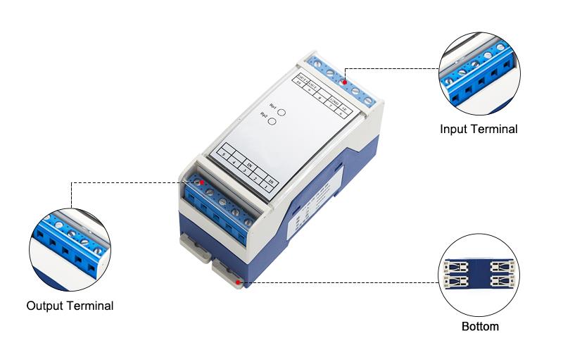
2. For the wire terminal connections, are all 6 terminals identical? What wire range can they accept? What is the depth or, at the very least, the recommended wire strip length?
3. In the attached pdf page 4, can you verify there is a typo in the right-side wiring diagram for the input pin? The website shows 3, the catalog shows 1. We assume 3 is correct. How does the wire get secured – are they screwed down or some kind of spring terminal?
This SKU ATO-VOS-DC70 is out of stock.
We recommend you another isolated DC voltage sensor ATO-VOS-DC1000, which has measuring range from DC 10mV, 50mV, 75mV, 5V, 75V, 150V, 300V, 500V to 1000V.
DC voltage sensor has measuring range of 100mV/1V/10V/50V to 70V.
Specification:
| Model | ATO-WBV144H21-AS | |
| Shipping weight | 1kg | |
| Measuring range of input voltage * | DC 0-100mV ~ 0-70V | |
| Short-time overload | 2 times of nominal input voltage, 1s in duration, interval time 10s, repeat 10 times | |
| Linear measurement range | 0% ~ 120% measuring range | |
| Input impedance | When Ux>1V, Ri=Ux*10kΩ/V; when Ux≤1V, Ri≥1MΩ | |
| Output signal | DC 4-20mA | |
| Power supply * | DC 12V, 24V | |
| Accuracy | 0.5%F.S. | |
| Load capacity | 300Ω | |
| Response time | ≤250ms | |
| Temperature drift | 300*10-6/℃ | |
| Isolation features | Isolation between input and output, output terminals provides power supply | |
| Isolation voltage | AC 2kV, 1 min | |
| Work temperature | -10~+60℃ | |
| Storage temperature | -25~+70℃ | |
| Protection features | Surge (inrush) immunity: Output/power supply 2kV 1.2/50μs Electrostatic discharge immunity: Contact discharge 6kV, air discharge 8kV Radio frequency electromagnetic field radiation immunity: A Electrical fast transient burst immunity: Signal line port ±2kV, power supply port ±2kV Conducted immunity of radio frequency electromagnetic field: A Inrush current: Input port common mode 5kA, differential mode 3kA, 8/20μs | |
| Mean time between failures | >50000h | |
| Housing material | Fire-retardant ABS | |
| Wiring | Terminal connection | |
| Installation | DIN rail (NS35/7.5, NS35/15, EN50022) | |
DC voltage sensor 100mV to 70V dimensional drawing (unit: mm):
DC voltage sensor 100mV to 70V wiring diagram: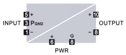
Details
Related products

Isolated DC Voltage Sensor 10mV to 1000V, Power Supply DC 12V/24V
ATO-VOS-DC1000
$141.96
DC voltage sensor uses modulation and demodulation technology to achieve input/output/power supply isolation. Isolated voltage transducer has measuring range from DC 10mV/50mV/75mV/5V/150V/300V/500V to 1000V, supply voltage DC 12V/24V, accuracy 0.2%FS, output signal 0-5V/0-10V/0-20mA/4-20mA and strong anti-interference capability. DC voltage sensor is widely used for voltage isolated measuring and control, such as electric power, remote monitoring, medical equipment, etc.

Voltage Sensor for DC Bidirectional Voltage, Power Supply 12V/15V/24V
ATO-VOS-BDC1000
$169.96
DC voltage sensor with supply voltage DC 12V/15V/24V is a special voltage sensor for bidirectional voltage tracking. The measuring range of input voltage is from ±50mV, ±50V, ±200V, ±500V to ±1000V. The output signal can be DC 2.5±2.5V, 5±5V, 12±8mA, or 10±10mA.

Isolated DC Voltage Sensor for Ripple Voltage 10mV to 1000V
ATO-VOS-RDC1000
From $134.81
DC voltage sensor is a special voltage sensor for unidirectional ripple DC voltage measurement. It has a measuring range from DC 10mV/50mV/75mV/5V/150V/300V/500V to 1000V, output signal 0-5V/0-10V/0-20mA/4-20mA, supply voltage DC 12/24V, IP20 and DIN rail installation. Isolated DC voltage transducer uses modulation and demodulation technology to achieve input/output/power supply isolation.

AC/DC Voltage Sensor 75mV to 500V, RMS 0-5V/0-10V/4-20mA/0-20mA Output
ATO-VOS-ACDC500
$161.27
Voltage sensor has voltage measuring range from AC/DC 75mV/50V/100V/250V/300V to 500V, supply voltage DC 12V/24V, output DC voltage/current or True RMS voltage/current signal 0-5V/0-10V/0-20mA/4-20mA and protection class IP20. AC/DC voltage sensor has two installation methods, DIN rail installation and M3 screw fixation.