300 W DC Worm Gear Motor, 12V/24V/48V

$662.75
Economical price 300 W DC worm gear motor for sale, it is a 3 phase brushless motor and worm gearbox providing high torque and high efficiency at 12V, 24V, 36V or 48V, gear ratio from 7.5:1 to 80:1, 2000 rpm rated speed, rated torque at 0.96N·m and peak torque at 2.88N·m.
SKU: ATO-GEAR-W300
*
*
Free Shipping
Delivery date: 6-25 days

300W BLDC motor matches with worm gearbox providing high torque at 12V, 24V or 48V power supply, gear ratio from 7.5:1 to 100:1 available, high speed and high performance.

Specification

Motor ModelATOD5BLD300-12AATOD5BLD300-24AATOD5BLD300-36AATOD5BLD300-48A
Motor TypeBLDC Motor
Power300W
Voltage12V DC24V DC36V DC48V DC
Rated Current31.25A15.63A10.42A7.81A
No Load Current<7.2A<6.13A<3.5A<4.61A
No Load Speed2700 rpm
Rated Speed2000 rpm
Rated Torque0.96N·m
Peak Torque2.88N·m
Motor Dimension86mm
Shaft Diameter11mm
ConstructionPermanent Magnet
Direction of RotationCW/CCW
CertificateCCC, CE, ROSH, LVD, EMC
Gear Ratio7.5, 10, 15, 20, 25, 30, 40, 50, 60, 80, 100
Recommended Drive ModelATO-KVD2412NATO-BLD750ATO-BLD750ATO-BLD300B
What Parameters of ATO Worm Gear Motors Can Be Customized?
PowerYes
VoltageYes
SpeedYes
ShaftYes
Motor LengthYes
Motor LeadYes

Allowable Torque with Gear Head

Gear Ratio7.5101520253040506080100
Rated Output Speed (rpm)26720013310080675040332520
Rated Output Torque (Nm)6.48.612.917.232.036.032.038.028.034.029.0

Note:

  • This torque value is the rated output value of the reducer, not the final motor + output torque value T after reducer.
  • The formula for calculating the output torque after the final motor + reducer: T = rated torque of the motor * reduction ratio * 0.6, and T≤ rated allowable output torque value of the reducer.

Dimensions (Unit: mm)

Mounting screws are included with gearhead
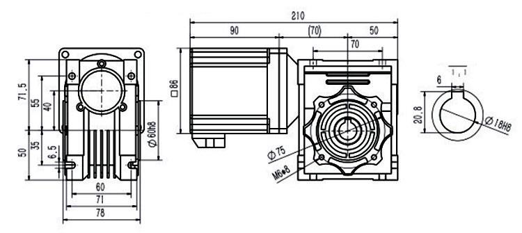
Dimensions of 300 W DC Worm Gear Motor

Speed-Torque Curve

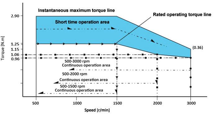
300 W DC Worm Gear Motor Speed Torque Curve

  • Instantaneous maximum torque line
    The maximum torque momentarily impacts the load when the motor is started.
    Beyond this torque, the over-current protection of the driver will cause the motor to stop.
  • Short time operation area
    The motor can run at a short time within this torque range at different speeds.
    If the operation time is too long, the motor will generate heat, which may cause the motor to stop or burn.
  • Rated operating torque line
    The rated torque of motor running at different speeds, and the motor can run for a long time at this torque.
  • Continuous operating area
    When the motor rotates at different speeds, it runs continuously in this corresponding zone.

Details
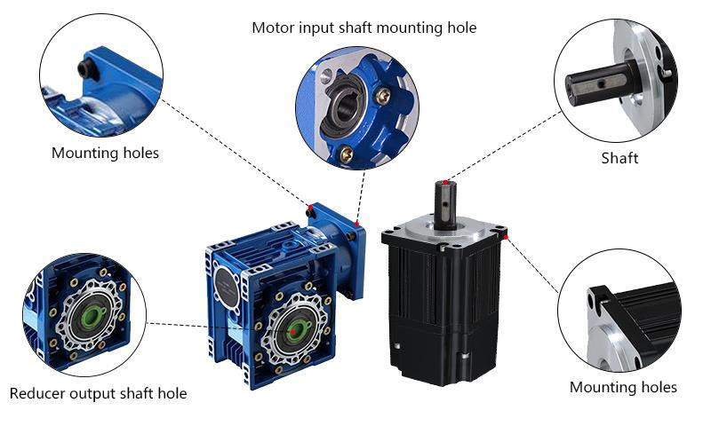
300W DC Worm Gear Motor Details

Tips: Difference between a DC worm gear motor and a gear motor?

Worm gear motor and gear motor are two widely used reduction equipment. Worm gear motor is a kind of power transmission mechanism that uses gear speed converter to decelerate the number of revolutions of the motor to the required number of revolutions and obtain a larger torque. In the mechanism used to transmit power and motion, the application range of the reducer is quite wide.

The basic structure of the worm gear motor is mainly composed of the driving parts worm gear, shaft, bearing, box and its accessories. It can be divided into three basic structural parts: box body, worm gear, bearing and shaft combination. The box body is the base of all the accessories in the worm gear motor. It is an important accessory that supports the fixed shaft system components, the correct relative position of the drive accessories, and supports the load acting on the reducer. The main function of the worm gear motor is to transmit the motion and power between the two interleaved shafts, and the main function of the bearing and the shaft is to transmit power, operate and improve efficiency.

Gear motor is generally used for low-speed and high-torque driving equipment. The ordinary reducer of the motor will also have several pairs of gears with the same principle to achieve the ideal deceleration effect. The ratio of the number of teeth of the large and small gears is the drive ratio.

Gear motor is a drive device enclosed in a rigid box. It consists of several gear drive groups, shafts, bearings, output shafts and other parts. It can be used to change the speed and torque between the input shaft and the output shaft. The gear motor uses all levels of gear drive to achieve the purpose of speed reduction. The reducer is composed of various levels of gear pairs. For example, a small gear can be used to drive a large gear to achieve a certain reduction purpose, and then a multi-stage structure is adopted, which can greatly reduce the speed.

VFD Two-Wire Control Wiring with Push Button for Forward Motor

In this video we've guided you through how to do VFD control wiring with a self-lock push button switch to run the motor in forward direction. We've covered everything from wiring to programming and even a test run. So just watch it through and hope you'll find it informative and helpful.

Product reviews
Great quality.
5
Henderson
Avatar
4/18/2022 9:58 PM
I like this worm DC gear motor. Runs exactly at the speed specified, lots of torque, strong shaft and gears, decently high torque and perfect for the robotic arm I’m building. Easy to use and control. I would recommends this product in a heartbeat.
Was this review helpful? Yes No (0/0)
Write your review
  • Only registered users can write reviews
*
*
  • Bad
  • Excellent
*
*
*
*

300W BLDC motor matches with worm gearbox providing high torque at 12V, 24V or 48V power supply, gear ratio from 7.5:1 to 100:1 available, high speed and high performance.

Specification

Motor ModelATOD5BLD300-12AATOD5BLD300-24AATOD5BLD300-36AATOD5BLD300-48A
Motor TypeBLDC Motor
Power300W
Voltage12V DC24V DC36V DC48V DC
Rated Current31.25A15.63A10.42A7.81A
No Load Current<7.2A<6.13A<3.5A<4.61A
No Load Speed2700 rpm
Rated Speed2000 rpm
Rated Torque0.96N·m
Peak Torque2.88N·m
Motor Dimension86mm
Shaft Diameter11mm
ConstructionPermanent Magnet
Direction of RotationCW/CCW
CertificateCCC, CE, ROSH, LVD, EMC
Gear Ratio7.5, 10, 15, 20, 25, 30, 40, 50, 60, 80, 100
Recommended Drive ModelATO-KVD2412NATO-BLD750ATO-BLD750ATO-BLD300B
What Parameters of ATO Worm Gear Motors Can Be Customized?
PowerYes
VoltageYes
SpeedYes
ShaftYes
Motor LengthYes
Motor LeadYes

Allowable Torque with Gear Head

Gear Ratio7.5101520253040506080100
Rated Output Speed (rpm)26720013310080675040332520
Rated Output Torque (Nm)6.48.612.917.232.036.032.038.028.034.029.0

Note:

  • This torque value is the rated output value of the reducer, not the final motor + output torque value T after reducer.
  • The formula for calculating the output torque after the final motor + reducer: T = rated torque of the motor * reduction ratio * 0.6, and T≤ rated allowable output torque value of the reducer.

Dimensions (Unit: mm)

Mounting screws are included with gearhead

Dimensions of 300 W DC Worm Gear Motor

Speed-Torque Curve

300 W DC Worm Gear Motor Speed Torque Curve

  • Instantaneous maximum torque line
    The maximum torque momentarily impacts the load when the motor is started.
    Beyond this torque, the over-current protection of the driver will cause the motor to stop.
  • Short time operation area
    The motor can run at a short time within this torque range at different speeds.
    If the operation time is too long, the motor will generate heat, which may cause the motor to stop or burn.
  • Rated operating torque line
    The rated torque of motor running at different speeds, and the motor can run for a long time at this torque.
  • Continuous operating area
    When the motor rotates at different speeds, it runs continuously in this corresponding zone.

Details

300W DC Worm Gear Motor Details

Tips: Difference between a DC worm gear motor and a gear motor?

Worm gear motor and gear motor are two widely used reduction equipment. Worm gear motor is a kind of power transmission mechanism that uses gear speed converter to decelerate the number of revolutions of the motor to the required number of revolutions and obtain a larger torque. In the mechanism used to transmit power and motion, the application range of the reducer is quite wide.

The basic structure of the worm gear motor is mainly composed of the driving parts worm gear, shaft, bearing, box and its accessories. It can be divided into three basic structural parts: box body, worm gear, bearing and shaft combination. The box body is the base of all the accessories in the worm gear motor. It is an important accessory that supports the fixed shaft system components, the correct relative position of the drive accessories, and supports the load acting on the reducer. The main function of the worm gear motor is to transmit the motion and power between the two interleaved shafts, and the main function of the bearing and the shaft is to transmit power, operate and improve efficiency.

Gear motor is generally used for low-speed and high-torque driving equipment. The ordinary reducer of the motor will also have several pairs of gears with the same principle to achieve the ideal deceleration effect. The ratio of the number of teeth of the large and small gears is the drive ratio.

Gear motor is a drive device enclosed in a rigid box. It consists of several gear drive groups, shafts, bearings, output shafts and other parts. It can be used to change the speed and torque between the input shaft and the output shaft. The gear motor uses all levels of gear drive to achieve the purpose of speed reduction. The reducer is composed of various levels of gear pairs. For example, a small gear can be used to drive a large gear to achieve a certain reduction purpose, and then a multi-stage structure is adopted, which can greatly reduce the speed.

Product reviews
Great quality.
5
Henderson
Avatar
4/18/2022 9:58 PM
I like this worm DC gear motor. Runs exactly at the speed specified, lots of torque, strong shaft and gears, decently high torque and perfect for the robotic arm I’m building. Easy to use and control. I would recommends this product in a heartbeat.
Was this review helpful? Yes No (0/0)
Only registered users can write reviews