20hp (15kW) 3-Phase Asynchronous Motor with Clutch

$7,973.87
Lower cost three phase asynchronous motor with clutch, 15000 watt, with rated torque 94.3Nm, working voltage of 380V 50Hz, widely used in textile, chemical, metallurgy, building materials, paper making, plastic and other industries.
SKU: ATO-AMWC-15000W
*
Ship to
*
*
Shipping Method
Name
Estimated Delivery
Price
No shipping options
Delivery date: 10-20 days

Totally enclosed 3-phase asynchronous motor with clutch, with rated output 20hp, rated speed 1250rpm in foot mounting. It offers high-efficiency performance, high starting torque, little vibration, and reliable operation.

20hp (15kW) 3-Phase Asynchronous Motor with Clutch Specification

ModelATO-YCT225-4B
Capacity15kW
Rated Torque94.3Nm
Speed adjustable Range1250-125r/min
Speed Changing Rate3%
Rated Voltage380V
InstallationB3
Frequency50Hz
Phase3 phase
CertificationCE, CCC, IS9001, IS2008
IP GradeIP21
EfficiencyIE1/IE2/IE3
FrameCast Iron or aluminum
Weight250kg
Ambient temperature-15℃~40℃
Altitudenot exceeding 1000 Meters
DutyContinuous running
Insulation GradeB
Warranty1 year

20hp (15kW) 3-Phase Asynchronous Motor with Clutch Dimensions
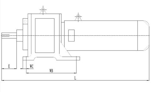

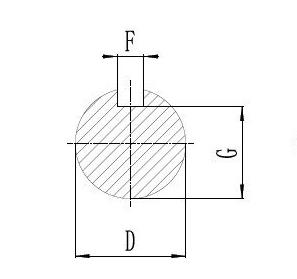
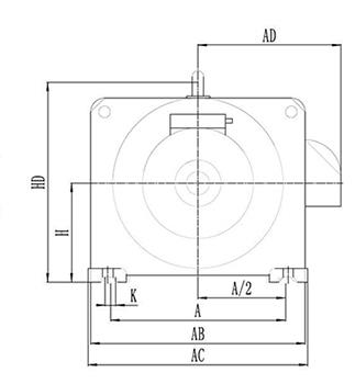
3 phase asynchronous motor dimensions3 phase asynchronous motor dimensions3 phase asynchronous motor dimensions

ModelYCT225-4B
Mounting Dimension & Tolerance (mm)ABasic Size356
A/2Basic Size178
WBBasic Size406
WCBasic Size56
Limit Size±1.5
DBasic Size42
Limit Tolerance+0.018   +0.002
EBasic Size110
Limit Tolerance±0.43
FBasic Size12
Limit Tolerance-0.043
GBasic Size37
Limit Tolerance-0.2
HBasic Size225
Limit Tolerance-0.5
KBasic Size19
Limit Tolerance‘+0.52
Position ToleranceΦ 1.5 Ⓜ
Mounting Dimension & Tolerance (mm)AB465
AC485
AD270
HD545
L980

Details

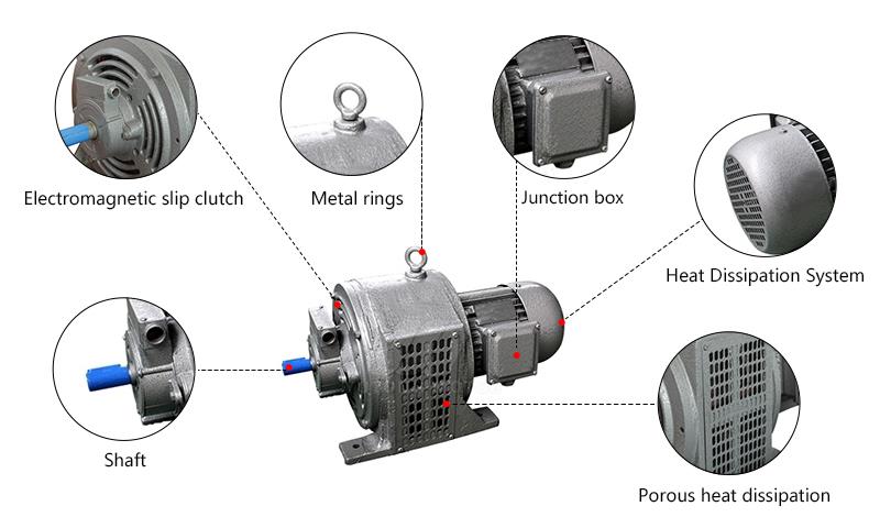
15000W Asynchronous Motor with Clutch Details

Tips: Working Principle of 20hp (15kW) 3-Phase Asynchronous Motor with Clutch.

When a symmetrical three-phase alternating current is passed into the three-phase stator winding, a rotating magnetic field is generated that rotates at a synchronous speed n1 along the inner circular space of the stator and rotor. Since the rotating magnetic field rotates at n1 speed, the rotor conductor is stationary at the beginning, so the rotor conductor will cut the stator rotating magnetic field and generate the induced electric potential (the direction of the induced electric potential is determined by the right-hand rule). As the rotor conductor is shorted at both ends by the shorting ring, under the action of the induced electromotive force, the rotor conductor will generate an induced current in the same direction as the induced electromotive force. The current-carrying conductor of the rotor is subjected to an electromagnetic force in the stator magnetic field (the direction of the force is determined by the left-hand rule). The electromagnetic force produces an electromagnetic torque on the rotor shaft, which drives the rotor to rotate in the direction of the rotating magnetic field.

Through the above analysis, we can conclude that the working principle of motor is as follows: when the three-phase stator winding of motor (each phase is 120 degrees different from the other) is connected to the three-phase symmetrical alternating current, a rotating magnetic field will be generated, which will cut the rotor winding and produce induction current in the rotor winding (the rotor winding is a closed path), the current-carrying rotor conductor will produce electromagnetic force under the action of the rotating stator magnetic field, which will form electromagnetic torque on the rotor shaft. The current-carrying rotor conductor will generate electromagnetic force under the stator rotating magnetic field, thus forming electromagnetic torque on the motor shaft to drive the motor rotation, and the direction of motor rotation is the same as the direction of rotating magnetic field.

Three-phase Motor to Single-phase (380V to 220V)
If a frequency converter is beyond your budget or availability, one way to run a three-phase motor from single-phase power is to use capacitors. In this tutorial, the step-by-step process of adapting a motor for single-phase operation is demonstrated by showing the correct capacitor sizing and wiring configuration.

In this video we've guided you through how to do VFD control wiring with a self-lock push button switch to run the motor in forward direction. We've covered everything from wiring to programming and even a test run. So just watch it through and hope you'll find it informative and helpful.

Write your review
  • Only registered users can write reviews
*
*
  • Bad
  • Excellent
*
*
*
*

Totally enclosed 3-phase asynchronous motor with clutch, with rated output 20hp, rated speed 1250rpm in foot mounting. It offers high-efficiency performance, high starting torque, little vibration, and reliable operation.

20hp (15kW) 3-Phase Asynchronous Motor with Clutch Specification

ModelATO-YCT225-4B
Capacity15kW
Rated Torque94.3Nm
Speed adjustable Range1250-125r/min
Speed Changing Rate3%
Rated Voltage380V
InstallationB3
Frequency50Hz
Phase3 phase
CertificationCE, CCC, IS9001, IS2008
IP GradeIP21
EfficiencyIE1/IE2/IE3
FrameCast Iron or aluminum
Weight250kg
Ambient temperature-15℃~40℃
Altitudenot exceeding 1000 Meters
DutyContinuous running
Insulation GradeB
Warranty1 year

20hp (15kW) 3-Phase Asynchronous Motor with Clutch Dimensions

3 phase asynchronous motor dimensions3 phase asynchronous motor dimensions3 phase asynchronous motor dimensions

ModelYCT225-4B
Mounting Dimension & Tolerance (mm)ABasic Size356
A/2Basic Size178
WBBasic Size406
WCBasic Size56
Limit Size±1.5
DBasic Size42
Limit Tolerance+0.018   +0.002
EBasic Size110
Limit Tolerance±0.43
FBasic Size12
Limit Tolerance-0.043
GBasic Size37
Limit Tolerance-0.2
HBasic Size225
Limit Tolerance-0.5
KBasic Size19
Limit Tolerance‘+0.52
Position ToleranceΦ 1.5 Ⓜ
Mounting Dimension & Tolerance (mm)AB465
AC485
AD270
HD545
L980

Details

15000W Asynchronous Motor with Clutch Details

Tips: Working Principle of 20hp (15kW) 3-Phase Asynchronous Motor with Clutch.

When a symmetrical three-phase alternating current is passed into the three-phase stator winding, a rotating magnetic field is generated that rotates at a synchronous speed n1 along the inner circular space of the stator and rotor. Since the rotating magnetic field rotates at n1 speed, the rotor conductor is stationary at the beginning, so the rotor conductor will cut the stator rotating magnetic field and generate the induced electric potential (the direction of the induced electric potential is determined by the right-hand rule). As the rotor conductor is shorted at both ends by the shorting ring, under the action of the induced electromotive force, the rotor conductor will generate an induced current in the same direction as the induced electromotive force. The current-carrying conductor of the rotor is subjected to an electromagnetic force in the stator magnetic field (the direction of the force is determined by the left-hand rule). The electromagnetic force produces an electromagnetic torque on the rotor shaft, which drives the rotor to rotate in the direction of the rotating magnetic field.

Through the above analysis, we can conclude that the working principle of motor is as follows: when the three-phase stator winding of motor (each phase is 120 degrees different from the other) is connected to the three-phase symmetrical alternating current, a rotating magnetic field will be generated, which will cut the rotor winding and produce induction current in the rotor winding (the rotor winding is a closed path), the current-carrying rotor conductor will produce electromagnetic force under the action of the rotating stator magnetic field, which will form electromagnetic torque on the rotor shaft. The current-carrying rotor conductor will generate electromagnetic force under the stator rotating magnetic field, thus forming electromagnetic torque on the motor shaft to drive the motor rotation, and the direction of motor rotation is the same as the direction of rotating magnetic field.

Only registered users can write reviews