Solid state relay SSR-60AA, 60A 70-280V AC to AC

$63.26
Brand new SSR-60AA solid state relay, 60A load current, AC control, 70-280V AC input voltage, 24-480V AC load voltage, zero cross, LED indicator, panel mount. Hight quality yet low cost.
SKU: ATO-SSR-DH60AA
Free Shipping
Delivery date: 6-12 days

Features

60A 70-280V AC to 24-480V AC solid state relay (SSR) features high structural strength, good impact resistance, and strong shock resistance. The SSR offers a reliable switching the commercial and industrial loads, such as computer peripheral interface device, printing machine, molding machine, food machine, packaging machine, and so on.

  • Built in RC absorption
  • Photoelectric isolation
  • SCR output
  • LED indicator for operation status
  • Removable protective cover for safety
  • Panel mount
  • Zero-crossing switch type

Specification

ModelATO-SSR-DH60AA
InputControl voltage range70-280V AC
Max. input current15mA
Must operate voltage70V AC
Must release voltage50V AC
OutputLoad voltage range24-480V AC
Peak voltage800V AC
Maximum load current60A
Maximum off-state leakage current2mA
Maximum off-state time10mS
Maximum on-state voltage drop1.5V
GeneralTypeAC to AC, single phase
Dimension L – W – H (mm)57.4х44.8х28
Weight135g
Dielectric strength (input to output)4000V
Dielectric strength (input, output to the base)2500V
Operating temperature-20℃~ 80℃
MountPanel
CertificationCE

Note:

  1. When the load is a resistive load, the maximum load current of the selected SSR should be 2~3 times greater than the actual load current;
  2. When the load is an inductive load, the maximum load current of the selected SSR should be more than 7~8 times the actual load current.
  3. When the maximum load current is higher than 10A, a heat sink must be installed to the solid state relay, or the SSR relay should be mounted on a metal base plate with heat dissipation effect, and the thermal grease is applied between them.

Dimension (Unit: mm)
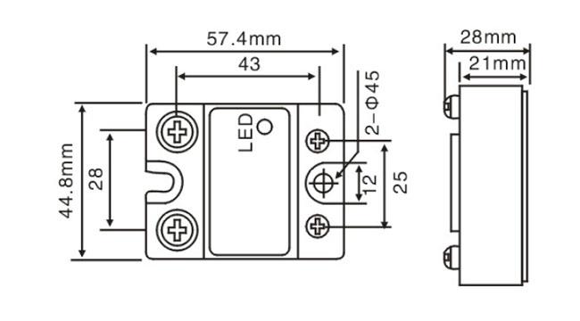
Single Phase SSR Dimensions

Wiring Diagram

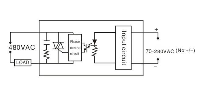
Single Phase AC to AC SSR Wiring DiagramTips: AC solid state relays vs DC solid state relays

Based on the type of load power supply, SSRs can be divided into AC Solid State Relays (AC-SSRs) and DC Solid State Relays (DC-SSRs). AC-SSRs use a bidirectional thyristor as a switching device to turn on or off the AC load power supply. According to the type of control trigger, AC-SSR can be divided into zero-crossing and random turn-on. Zero-crossing AC-SSRs switch on when AC power supply goes through approx. zero voltage after control signals input. Therefore, their interference is small. The random turn-on AC-SSRs switch on or off in any phase of the AC power supply, so there may be more interference the moment they turn on.

Compared with AC-SSR, DC-SSR has no zero-crossing control circuit and does not need to install a absorption circuit, and its switching devices generally use high-power switching transistor, except which, they have the same working principles. When DC-SSR is used, it should be noted that:

  1. In the case of inductive load, such as DC solenoid valves or electromagnets, a diode should be set in parallel at both ends of the load. Meanwhile, its current should be equal to the operating current, and its voltage should be 4 times greater than the operating voltage.
  2. During its operation, try to put SSR close to the load, and its output lead should meet the needs of the load current.
  3. Its filtering electrolytic capacitor should be large enough when the used power supply is obtained by AC brownout rectification.

Solid state relay (SSR) is simple but widely used in the automation fields. Thus, it is not complex to wire a solid state relay. In this vedio, ATO takes a 40 Amp SSR (DC - AC) for example to show the wiring of a SSR and then switch on/off a motor with this SSR.

How to Test a Solid State Relay?

Solid state relays are commonly used to control many electronic components, so if a component isn't working because there's no current flowing through it, it's likely a problem with the relay. With some simple troubleshooting steps, it's easy to check if an SSR is working as expected. In this video, we'll show you step-by-step instructions on how to test a solid state relay.

Types of Solid State Relays

There are different types of solid state relays according to various classification standards. In this video, we will introduce a series of different types of SSRs according to the following standards.

DC-AC/AC-AC Single Phase Solid State Relays

In this video we take a quick look at ATO's current single phase SSR models along with their specifications and key features. They are designed to operate high load currents using low control currents, using our advanced opto-isolation technology.

In this video we will try to clear the confusion many people have between relays and contactors by showing you how to tell the difference based on five criteria: Definition, Capacity, Structure, Contacts and Applications.

Product reviews
Control well pump
5
Guyenng
Avatar
11/20/2022 11:12 PM
With this solid state relay, I just needed a small float switch and a tiny 5V solar panel to provide a few milliamperes for control power. Highly recommended!!!
Was this review helpful? Yes No (0/0)
Write your review
  • Only registered users can write reviews
*
*
  • Bad
  • Excellent
*
*
*
*

Features

60A 70-280V AC to 24-480V AC solid state relay (SSR) features high structural strength, good impact resistance, and strong shock resistance. The SSR offers a reliable switching the commercial and industrial loads, such as computer peripheral interface device, printing machine, molding machine, food machine, packaging machine, and so on.

  • Built in RC absorption
  • Photoelectric isolation
  • SCR output
  • LED indicator for operation status
  • Removable protective cover for safety
  • Panel mount
  • Zero-crossing switch type

Specification

ModelATO-SSR-DH60AA
InputControl voltage range70-280V AC
Max. input current15mA
Must operate voltage70V AC
Must release voltage50V AC
OutputLoad voltage range24-480V AC
Peak voltage800V AC
Maximum load current60A
Maximum off-state leakage current2mA
Maximum off-state time10mS
Maximum on-state voltage drop1.5V
GeneralTypeAC to AC, single phase
Dimension L – W – H (mm)57.4х44.8х28
Weight135g
Dielectric strength (input to output)4000V
Dielectric strength (input, output to the base)2500V
Operating temperature-20℃~ 80℃
MountPanel
CertificationCE

Note:

  1. When the load is a resistive load, the maximum load current of the selected SSR should be 2~3 times greater than the actual load current;
  2. When the load is an inductive load, the maximum load current of the selected SSR should be more than 7~8 times the actual load current.
  3. When the maximum load current is higher than 10A, a heat sink must be installed to the solid state relay, or the SSR relay should be mounted on a metal base plate with heat dissipation effect, and the thermal grease is applied between them.

Dimension (Unit: mm)

Single Phase SSR Dimensions

Wiring Diagram

Single Phase AC to AC SSR Wiring DiagramTips: AC solid state relays vs DC solid state relays

Based on the type of load power supply, SSRs can be divided into AC Solid State Relays (AC-SSRs) and DC Solid State Relays (DC-SSRs). AC-SSRs use a bidirectional thyristor as a switching device to turn on or off the AC load power supply. According to the type of control trigger, AC-SSR can be divided into zero-crossing and random turn-on. Zero-crossing AC-SSRs switch on when AC power supply goes through approx. zero voltage after control signals input. Therefore, their interference is small. The random turn-on AC-SSRs switch on or off in any phase of the AC power supply, so there may be more interference the moment they turn on.

Compared with AC-SSR, DC-SSR has no zero-crossing control circuit and does not need to install a absorption circuit, and its switching devices generally use high-power switching transistor, except which, they have the same working principles. When DC-SSR is used, it should be noted that:

  1. In the case of inductive load, such as DC solenoid valves or electromagnets, a diode should be set in parallel at both ends of the load. Meanwhile, its current should be equal to the operating current, and its voltage should be 4 times greater than the operating voltage.
  2. During its operation, try to put SSR close to the load, and its output lead should meet the needs of the load current.
  3. Its filtering electrolytic capacitor should be large enough when the used power supply is obtained by AC brownout rectification.
Product reviews
Control well pump
5
Guyenng
Avatar
11/20/2022 11:12 PM
With this solid state relay, I just needed a small float switch and a tiny 5V solar panel to provide a few milliamperes for control power. Highly recommended!!!
Was this review helpful? Yes No (0/0)
Only registered users can write reviews