
Nema 23 Stepper motor, 3.0Nm in 111mm, 1.8 degree, manufacturer direct sale.
Specification
| Electrical Specification | Model | ATO57STH111-4004 |
| Matched Driver Model | ATODSP57(Click it to see more info) | |
| Step Angle | 1.8° | |
| Holding Torque | 3.0Nm | |
| Rated Current/phase | 4.2A | |
| Phase Resistance | 0.9Ω | |
| Inductance | 3.8mH | |
| Rotor Inertia | 800g-cm2 | |
| Physical Specification | Frame Size | 57 x 57mm |
| Length | 111mm | |
| Shaft Diameter | Φ6.35mm | |
| Shaft Length | 19mm | |
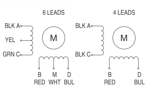
| Motor Leads | 4 | |
| Weight | 1.4kg | |
| Technical Parameters | Step Angle Accuracy | ±5% (full step, no load) |
| Resistance Accuracy | ±10% | |
| Inductance Accuracy | ±20% | |
| Temperature Rise | 80℃ Max. (rated current, 2 phase on) | |
| Ambient Temperature | -20℃~+50℃ | |
| Insulation Resistance | 100MΩ Min. 500VDC | |
| Dielectric Strength | 500V AC for one minute | |
| Shaft Radial Play | 0.02Max. 450g | |
| Shaft Axial Play | 0.08Max. 450g | |
| Quality Assurance | Warranty Period | 12 months |
| Certificate | CE, ROHs, ISO/SGS9001 |
Dimensions: (Unit=mm)
 L Max=111mm
Wiring Diagram
 Tips: Solutions to interference of stepper motor
- Install power filter to reduce the contamination of AC power.
- Based on the principle of “single-point-earthing”, connect all the following earthing lines or something else to the earthing rod on wall of chassis, including grounding wire of power filter and stepper driver PE (the baseboard of driver and chassis should be insulated.), control pulse and direction pulse DIR-outgoing lines of short circuit, motor earthing line, cable protecting cover between driver and motor and shielded wire of driver, and good contact should be realized.
- Lengthen the distance between control line, power line (L and N) and motor drive line (U, V and W) to avoid crossing. For example, when dealing with the driver installation site of two drivers of the same chassis in the double-shaft system, put the nameplate of one driver forward and that of the other backward, and shorten the leads as far as possible when making structural arrangement.
- Reduce the external interference in power line with the shielded line or the interference of power line in external world.
Only registered users can write reviews
Related products

6-wire Nema 23 Stepper Motor, 2 phase, 2A, 1.8 degree
ATO-STEP-512302
$65.46
This is high quality Nema 23 stepper motor with 1.8 deg. step angle(200 steps/rev). Each phase draws current 2A, allowing for a holding torque of 0.72Nm. Motor type is Hybrid Stepper Motor. Direct sales by manufacturer.

6-wire Nema 23 Stepper Motor, 2 phase, 3A, 1.8 degree
ATO-STEP-512303
$65.46
Low cost Nema 23 hybrid stepper motor with 1.8 deg. step angle(200 steps/rev). Phase current 3A and holding torque 0.72Nm. 100% brand new and manufacturer direct sale.

High Torque Nema 23 Stepper Motor, 3A, 1.8 degree, 4 wires
ATO-STEP-822303
$73.92
Nema 23 stepper motor with high quality, 2.2Nm holding torque, 2 phase 4 wires, 1.8 deg. step angle, manufacturer direct sale.

High Torque Nema 23 Stepper Motor, 4A, 1.8 degree, 2 phase 4 wires
ATO-STEP-982304
$88.08
Nema 23 stepper motor features 1.8 deg. step angle (200 steps/revolution), 2.5Nm holding torque and 4A phase current. Brand new and direct sale by manufacturer.