

I’m interested in learning if your ATO HCL Gas Detector will work in our HCL acid scrubber emissions stack.
The following data represents the stack conditions:
Stack Area 6.1 FT2
Stack Gas Flow 7200 Dscfm
Stack Temp 140 degrees F
Water Vapor in the Stack 20%
HCL Concentration 2-16 ppm
ATO fixed HCL hydrogen chloride gas detector uses high quality sensors, and advanced micro-process technology, with data display and high/low alarm, fast response, high precision and good stability. Explosion proof, suitable for different kinds of situations.
Specification
| Model | GD300-HCL |
| Detection Principle | Electrochemistry |
| Gas | Hydrogen Chloride (HCl) |
| Range (Optional) | 0 to 10ppm, 0 to 20ppm, 0 to 50ppm, 0 to 100ppm, 0 to 200ppm |
| Resolution | 0.01ppm (0-10/20/50ppm), 0.1ppm (0-100/200ppm) |
| Calibration Kit | Gas pressure regulator (calibration gas cylinder NOT included) |
| Accuracy | ≤±3% F.S. |
| Response Time | ≤10s |
| Repeatability | ≤±1% |
| Recovery Time | ≤10s |
| Linearity Error | ≤±1% |
| Zero Shift | ≤±1% (F.S./year) |
| Signal Output (Optional) | 4-20mA and RS485 Relay output: one group of relay output (1NO+1NC, 5A/30V) for one alarm (default), or two groups of relay output (2NO+2NC, 5A/30V) for high/low alarm (optional). |
| Alarms | Sound, light |
| Display | High light nixie tube display |
| Installation | Wall-mounted, piping type, flow-type (according to the detected environment) |
| Connection | Power connection type: G1/2 male thread explosion-proof flexible pipe Pipe-mounted type: M45*P2.0 |
| Operating Time | 24h |
| Explosion-proof Grade | II 2G Ex db IIC T4 Gb |
| Protection Grade | IP65 |
| Certification | CE, ATEX (Standard: EN IEC 60079-0:2018, EN 60079-1:2014) |
| Working Voltage | 12-36V DC |
| Case Material | Die-casting aluminum housing |
| Operating Temperature | -20℃~50℃ |
| Operating Humidity | 0~95%RH (non-condensing) |
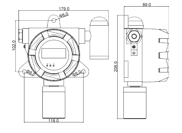
| Dimension | 206*179*90mm |
| Weight | ≤1.6kg |
| Power Adapter | Input 100-240VAC 50/60Hz, Output 24VDC 1A (Optional USA plug, Europe plug, AU plug or UK plug) |
| Accessories (Optional) | Calibration kit - gas pressure regulator (calibration gas cylinder NOT included)
|
Notes
Regarding the flow rate for gas detectors, there are 2 types:
- Pump-Suction Type: Equipped with a built-in pump, with a flow rate of 600 mL/min. (Models: GD200, GD400, GD600)
- Diffusion Type: Not equipped with a built-in pump, with a flow rate of 300 mL/min. (Models: GD300, GD500, GD800)
If you require a customized flow rate, please let us know your specific requirements. We will evaluate whether customization is possible. A flow rate that is too high or too low can affect measurement accuracy, so we recommend using an appropriate flow rate for your application.
Flow rate only needs to be considered when sampling gas from pipelines. For measuring gas concentrations in normal ambient air, you do not need to consider the flow rate. To measure confined spaces such as pipelines, please get in touch with us and provide the detailed conditions of use.
Dimensions (Unit: mm)
Installation Guide
The following precautions apply when connecting the GD300 series fixed gas detector to a pipeline:
- Working pressure should be stable at 1 bar ±10%, and the flow rate should be controlled at 300 mL/min.
- Working temperature is -20°C to +50°C.
- Working humidity is 0–95% RH. When the humidity is above 60% RH, it is recommended to use a dehumidifier or add a filter. When the humidity is above 95% RH, the gas is essentially saturated with water, making measurement impossible.
- The gas detector should be installed indoors. If it is installed outdoors, a rain cover should be added to protect the entire instrument.
- For the second pipeline connection method of the GD300 gas detector, the pipe-mounted installation, the detector mounting thread size is M45 × P2.0. During installation, hold the detector with both hands, keeping the sensor parallel to the mounting thread. Align it with the threaded port, rotate the detector clockwise, and install it in the desired position. To prevent gas leakage at the threaded connection, an appropriate amount of thread seal tape can be wrapped around the sensor head thread before installation.
***Other Common Gases and Ranges Available for Fixed Gas Detectors
| Gas Type | Measure Range | Resolution |
| Ammonia (NH3) | 0-50/100/200/500/1000/2000/5000ppm | 0.01ppm/0.1ppm/1ppm |
| Benzene (C6H6) | 0-1/10/50/100/200/1000/2000/5000/10000ppm | 0.001ppm/0.01ppm/0.1ppm/1ppm |
| Carbon Dioxide (CO2) | 0-1000/2000/5000/9999ppm, 0-2/5/10/20/25/30/50/100%VOL | 0.1ppm/1ppm/0.001%VOL/0.01%VOL/0.1%VOL |
| Carbon Monoxide (CO) | 0-10/20/50/100/500/1000/2000ppm | 0.01ppm/0.1ppm/1ppm |
| Chlorine (Cl2) | 0-5/10/20/50/100ppm | 0.001ppm/0.01ppm/0.1ppm |
| Chlorine Dioxide (ClO2) | 0-1/5/10/20/50/100ppm | 0.001ppm/0.01ppm/0.1ppm |
| Combustible Gas (EX) | 0-100%LEL | 1%LEL |
| Ethylene (C2H4) | 0-10/20/50/100/500/1000/2000ppm | 0.01ppm/0.1ppm/1ppm |
| Formaldehyde (CH2O) | 0-10/20/50/100/500/1000ppm | 0.01ppm/0.1ppm/1ppm |
| Hydrocarbons (HC) | 0-100%LEL | 1%LEL |
| Hydrogen (H2) | 0-10/20/500/1000/2000/5000/9999ppm, 0-2/4% VOL, 0-100% LEL | 0.1ppm/1ppm/0.001%VOL/1%LEL |
| Hydrogen Chloride (HCL) | 0-10/20/50/100/200ppm | 0.01ppm/0.1ppm |
| Hydrogen Cyanide (HCN) | 0-10/20/50/100ppm | 0.01ppm/0.1ppm |
| Hydrogen Sulfide (H2S) | 0-5/20/50/100/200ppm | 0.001ppm/0.01ppm/0.1ppm |
| Methane (CH4) | 0-50/100%VOL, 0-100%LEL | 0.01%VOL/0.1%VOL/1%LEL |
| Nitric Oxide (NO) | 0-1/5/10/20/50/100/250/500/1000ppm | 0.001ppm/0.01ppm/0.1ppm/1ppm |
| Nitrogen (N2) | 0-99.99/0-100%VOL | 0.01%VOL/0.1%VOL |
| Nitrogen Dioxide (NO2) | 0-1/5/10/20/50/100/500/1000ppm | 0.001ppm/0.01ppm/0.1ppm/1ppm |
| Nitrogen Oxides (NOX) | 0-1/5/10/20/50/100/250/500/1000ppm | 0.001ppm/0.01ppm/0.1ppm/1ppm |
| Oxygen (O2) | 0-25/30/100%VOL | 0.01%VOL/0.1%VOL |
| Ozone (O3) | 0-1/5/10/20/50/100ppm | 0.001ppm/0.01ppm/0.1ppm |
| Phosphine (PH3) | 0-10/20/50/100/500/1000/2000/3000ppm | 0.01ppm/0.1ppm/1ppm |
| Sulfur Dioxide (SO2) | 0-1/5/10/20/50/100/500/1000ppm | 0.001ppm/0.01ppm/0.1ppm/1ppm |
| Volatile Organic Compounds (VOC) | 0-1/5/10/20/50/100/200/500/1000/2000/5000/10000ppm | 0.001ppm/0.01ppm/0.1ppm/1ppm |
Note: Some common gases and the measuring ranges are listed in the above table. For more information, please feel free to contact us.
Details
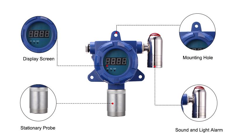
Application

Tips for installing a fixed gas detector
- Wiring should be done in the case of power failure, and the power should be turned on after confirming that the wiring is correct; the probe should be debugged by remote control when it is determined that there is no gas leakage on site.
- The installation location should be within a radius of 1 meter near the valve, pipe interface, air outlet or the place where it is easy to leak, as close as possible, but do not affect the operation of other equipment.
- When used for large-area gas detection, a probe can be arranged in 20-50 square meters, which can achieve the effect of safety monitoring.
- Installation height: When detecting gases lighter than air such as hydrogen, natural gas, city gas, etc., it is installed at a distance of about 1 meter above the roof; when detecting gases heavier than air such as liquefied petroleum gas, it is installed at a distance of 1.5-2 meters below the ground. Install about meters.
- The installation method can be roof hoisting, wall hanging or connecting pipes, etc. It should be ensured that the installation is firm and reliable. We are equipped with an infrared remote control to facilitate debugging and operation.
- The on-site wiring should be put through pipes, the pipes used should meet the fire protection requirements, and the pipes should be connected with the probe to meet the fire protection requirements.
- When installing, the sensor should be fixed downward.
- Shielded cables should be used for wiring. The diameter of a single wire is greater than 1 square millimeter. The shielding layer must be grounded when wiring.
Related products

Fixed Ethylene (C2H4) Gas Detector, 0 to 50/100/500/1000/2000 ppm
GD300-C2H4
$1,189.99
Factory price C2H4 Ethylene fixed gas detector with alarm light is a kind of monitoring gas concentration in different kinds of situations or pipelines 24h continuously wall mounted type gas detector, measuring range of 0 to 50/100/500/1000/2000ppm. Powered by 24V DC, with 4-20mA, RS485, relay signal output.

Fixed Hydrogen Cyanide (HCN) Gas Detector, 0 to 10/20/50/100 ppm
GD300-HCN
$1,126.99
Low price HCN hydrogen cyanide fixed gas detector, 0 to 10/20/50/100 ppm, with alarm light is a kind of monitoring gas concentration in different kinds of situations or pipelines 24h continuously wall mounted type gas detector. Powered by 24V DC, with 4-20mA, RS485, relay signal output.

Fixed Sulfur Dioxide (SO2) Gas Detector, 0 to 20/50/100 ppm
GD300-SO2
$935.99
Favorable price SO2 sulfur dioxide gas detector with alarm light is a 24h continuously wall mounted type gas detector which can detect SO2 in different kinds of situations. Measuring range 0 to 20/50/100 ppm, powered by 24V DC, with 4-20mA, RS485, relay signal output.

Portable Ethylene (C2H4) Gas Detector, 0 to 10/20/100/500/1000 ppm
GD200-C2H4
$1,001.59
Favorable price C2H4 ethylene gas detector is kind of mini size and high accuracy portable gas detector. The handheld ethylene gas detector with comprehensive functions, is easy to operate and suitable for different kinds of situations, measure range from 0 to 10/20/50/100/500/1000/200 ppm.