Digital Stepper Motor Driver, 3 phase, AC 90V ~ 230V

$211.29
Digital stepper motor driver works at AC 90V ~ 230V power supply, adjustable drive current 2.2A ~ 4.8A, which is capable of driving Nema 34 three phase hybrid stepper motors. A stepper controller and a bipolar stepper motor can form a stepper system for CNC machine and 3D printer.
SKU: ATO-STEP-M2205T
*
Free Shipping
Delivery date: 6-12 days

ATO digital stepper motor driver with adjustable voltage and current, is an ideal choice for three phase Nema 34 bipolar stepper motor solution. This stepper motor controller can realize precise position control even without a feedback system.

Features

  • Digital stepper motor driver is high performance, low price, low noise and good stability.
  • Adopt unique control circuit to increase high-speed response and smoothness.
  • Continuously adjustable drive current from 2.2A ~ 4.8A.
  • When the pulse stops exceeds 100ms, the coil current is automatically halved.
  • Average current control, two-phase sinusoidal current drive output.
  • Suitable for3 phase Nema 34, hybrid bipolar stepper motors.

Specification

ModelATO-FYTM2205T
Matched MotorNema 34 3 Phase Stepper Motor
VoltageAC 90V ~ 230V
Drive Current2.2A ~ 4.8A 16 Channels
Microstepping Setting60000 steps/rev 16 Channels
Hightest Pulse Frequency200Kpps
CertificationCE, FCC, RoHS
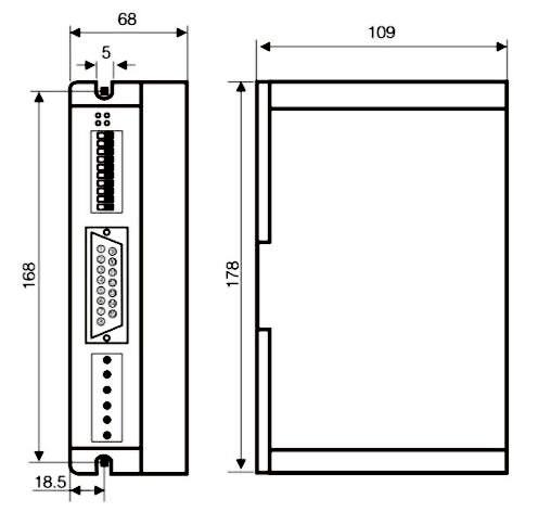
Dimensions178 x 108 x 67mm
Weight1kg
Function Description
FunctionsOperation Instructions
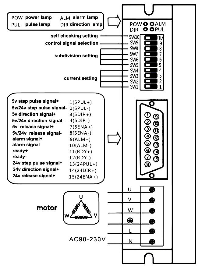
PUL+Positive End of Control Pulse SignalConnect to +5V power supply, +5V ~ +24V can be driven, higher than +5V need to connect current limiting resistor.
PUL-SW9=OFF, PUL is the pulse control signalThe falling edge is valid, and the motor takes one step whenever the pulse changes from high to low. Input resistance 220Ω. Requirements: low level 0 to 0.5V, high level 4 to 5V, pulse charge >2.5us. (This interface is shared with 24V negative pulse.)
SW9=ON, PUL is a positive pulse signal
DIR+Positive End of Directional SignalConnect to +5V power supply, +5V ~ +24V can be driven, higher than +5V need to connect current limiting resistor.
DIR-SW9=OFF, DIR is the direction control signalUsed to change the direction of the motor. Input resistance 220Ω. Requirements: low level 0 to 0.5V, high level 4 to 5V, pulse charge >2.5us. (This interface is shared with 24V negative pulse.)
SW9=ON, DIR is the reverse pulse signal
ENA+Positive End of Enabling SignalConnect to +5V power supply, +5V ~ +24V can be driven, higher than +5V need to connect current limiting resistor.
ENA-Negative End of Enabling SignalWhen it is valid (low level), the motor coil current is turned off, the driver stops working, and the motor is in a free state. (This interface is shared with 24V negative pulse.)
ALM+Positive End of Alarm Signal OutputWhen over-current, over-voltage, under-voltage or over-tolerance alarms, the alarm signal is valid (the output photocoupler is turned on). ALM+ is connected to the pull-up power to use the positive pole of the output power supply, and ALM- is connected to the negative pole of the output power supply. Maximum drive current 50mA.
ALM-Negative End of Alarm Signal Output
RDY+Positve End of Ready to Signal outputThe driver is in a normal state and is active when the controller signal is ready to accept (low level).
RDY-Negative End of Ready to Signal output
24PUL+Positive End of Signal Input+24V can be driven. (Its negative pulse interface is shared with 5V negative pulse interface.)
24DIR+Positive End of Signal Input+24V can be driven. (Its negative pulse interface is shared with 5V negative pulse interface.)
24ENA+Positive End of Signal Input+24V can be driven. (Its negative pulse interface is shared with 5V negative pulse interface.)

Operating Current Setting

Peak CurrentSW1SW2SW3SW4
2.2Aoffoffoffoff
2.4Aoffoffoffon
2.6Aoffoffonoff
2.8Aoffoffonon
3.0Aoffonoffoff
3.2Aoffonoffon
3.4Aoffononoff
3.6Aoffononon
3.8Aononoffoff
4.0Aononoffon
4.2Aonoffonoff
4.4Aonoffonon
4.6Aononoffoff
4.8Aononoffon

Microstep Segmentation Setting

Pulse/RevoSW5SW6SW7SW8
400onononon
500onononoff
600ononoffon
800ononoffoff
1000onoffonon
1200onoffonoff
2000onoffoffon
3000onoffoffoff
4000offononon
5000offononoff
6000offonoffon
10000offonoffoff
12000offoffonon
20000offoffonoff
30000offoffoffon
60000offoffoffoff

Dimensions (Unit: mm)

Dimensions of 3 Phase AC 90V-230V Digital Stepper Motor Driver

Wiring Diagram

Wiring Diagram of 3 Phase AC 90V 230V Digital Stepper Motor Driver

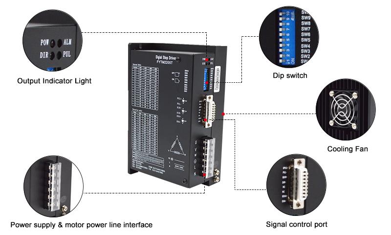
Details

3 Phase Digital Stepper Motor Driver AC 90v~230v Details

Tips: What is the advantage of stepper motor driver

The main advantage of stepper motor driver after subdivision is to completely eliminate the low frequency oscillation of the motor. Low frequency oscillation is an inherent characteristic of stepper motors, and subdivision is the only way to eliminate it. If your hybrid bipolar stepper motor sometimes needs to work in the resonance area, choosing a subdivision driver is the only choice. Improved the output torque of the motor. Especially for three-phase reactive motors, the torque ratio is increased by about 30-40% without subdivision, and the resolution of the motor is improved.

How to control a stepper motor using a PLC and HMI?
This video shows you how to configure a PLC, HMI, motor driver, and proximity sensor to perform Origin Return (OPR) control of a stepper motor.

Common Stepper Motor Troubleshooting Problems and Tips
In this video, 9 common problems that can occur with stepper motors are discussed, and expert advice is provided for diagnosing and effectively resolving these problems. If you have ever experienced problems with your stepper motor or want to be prepared for any future problems, this video is a must watch.

Product reviews
Makes driving a stepper motor simple and easy.
5
Mccurry
Avatar
4/14/2022 8:29 PM
I ordered this digital 3 phase stepper motor driver for my 3D printer which works properly with Nema 34 stepper motor. So far so good, easy setup and wiring. Works as described, and I would buy another one.
Was this review helpful? Yes No (0/0)
I want to buy this stepper motor driver.
5
Lizard
Avatar
7/27/2022 3:10 AM
I would like to purchase the above listed stepper motor driver that is matched to motor SKU: ATO-STEP-34M200. Is there a manual that comes with the driver? The stepper drive also lists a selection for an input pulse of 5v or 24v. Is this selection what is used for control of the drive and depends on my application? My application is to open and close doors, will have to be able to turn the motor both directions.
Was this review helpful? Yes No (0/0)
ATO Responded
Regarding your questions below,
1. Yes, our drives come with a manual.
2. Either 5v or 24v can be selected as input voltage.
3. The motor can be controlled forward and reverse by the controller.
Write your review
  • Only registered users can write reviews
*
*
  • Bad
  • Excellent
*
*
*
*

ATO digital stepper motor driver with adjustable voltage and current, is an ideal choice for three phase Nema 34 bipolar stepper motor solution. This stepper motor controller can realize precise position control even without a feedback system.

Features

  • Digital stepper motor driver is high performance, low price, low noise and good stability.
  • Adopt unique control circuit to increase high-speed response and smoothness.
  • Continuously adjustable drive current from 2.2A ~ 4.8A.
  • When the pulse stops exceeds 100ms, the coil current is automatically halved.
  • Average current control, two-phase sinusoidal current drive output.
  • Suitable for3 phase Nema 34, hybrid bipolar stepper motors.

Specification

ModelATO-FYTM2205T
Matched MotorNema 34 3 Phase Stepper Motor
VoltageAC 90V ~ 230V
Drive Current2.2A ~ 4.8A 16 Channels
Microstepping Setting60000 steps/rev 16 Channels
Hightest Pulse Frequency200Kpps
CertificationCE, FCC, RoHS
Dimensions178 x 108 x 67mm
Weight1kg
Function Description
FunctionsOperation Instructions
PUL+Positive End of Control Pulse SignalConnect to +5V power supply, +5V ~ +24V can be driven, higher than +5V need to connect current limiting resistor.
PUL-SW9=OFF, PUL is the pulse control signalThe falling edge is valid, and the motor takes one step whenever the pulse changes from high to low. Input resistance 220Ω. Requirements: low level 0 to 0.5V, high level 4 to 5V, pulse charge >2.5us. (This interface is shared with 24V negative pulse.)
SW9=ON, PUL is a positive pulse signal
DIR+Positive End of Directional SignalConnect to +5V power supply, +5V ~ +24V can be driven, higher than +5V need to connect current limiting resistor.
DIR-SW9=OFF, DIR is the direction control signalUsed to change the direction of the motor. Input resistance 220Ω. Requirements: low level 0 to 0.5V, high level 4 to 5V, pulse charge >2.5us. (This interface is shared with 24V negative pulse.)
SW9=ON, DIR is the reverse pulse signal
ENA+Positive End of Enabling SignalConnect to +5V power supply, +5V ~ +24V can be driven, higher than +5V need to connect current limiting resistor.
ENA-Negative End of Enabling SignalWhen it is valid (low level), the motor coil current is turned off, the driver stops working, and the motor is in a free state. (This interface is shared with 24V negative pulse.)
ALM+Positive End of Alarm Signal OutputWhen over-current, over-voltage, under-voltage or over-tolerance alarms, the alarm signal is valid (the output photocoupler is turned on). ALM+ is connected to the pull-up power to use the positive pole of the output power supply, and ALM- is connected to the negative pole of the output power supply. Maximum drive current 50mA.
ALM-Negative End of Alarm Signal Output
RDY+Positve End of Ready to Signal outputThe driver is in a normal state and is active when the controller signal is ready to accept (low level).
RDY-Negative End of Ready to Signal output
24PUL+Positive End of Signal Input+24V can be driven. (Its negative pulse interface is shared with 5V negative pulse interface.)
24DIR+Positive End of Signal Input+24V can be driven. (Its negative pulse interface is shared with 5V negative pulse interface.)
24ENA+Positive End of Signal Input+24V can be driven. (Its negative pulse interface is shared with 5V negative pulse interface.)

Operating Current Setting

Peak CurrentSW1SW2SW3SW4
2.2Aoffoffoffoff
2.4Aoffoffoffon
2.6Aoffoffonoff
2.8Aoffoffonon
3.0Aoffonoffoff
3.2Aoffonoffon
3.4Aoffononoff
3.6Aoffononon
3.8Aononoffoff
4.0Aononoffon
4.2Aonoffonoff
4.4Aonoffonon
4.6Aononoffoff
4.8Aononoffon

Microstep Segmentation Setting

Pulse/RevoSW5SW6SW7SW8
400onononon
500onononoff
600ononoffon
800ononoffoff
1000onoffonon
1200onoffonoff
2000onoffoffon
3000onoffoffoff
4000offononon
5000offononoff
6000offonoffon
10000offonoffoff
12000offoffonon
20000offoffonoff
30000offoffoffon
60000offoffoffoff

Dimensions (Unit: mm)

Dimensions of 3 Phase AC 90V-230V Digital Stepper Motor Driver

Wiring Diagram

Wiring Diagram of 3 Phase AC 90V 230V Digital Stepper Motor Driver

Details

3 Phase Digital Stepper Motor Driver AC 90v~230v Details

Tips: What is the advantage of stepper motor driver

The main advantage of stepper motor driver after subdivision is to completely eliminate the low frequency oscillation of the motor. Low frequency oscillation is an inherent characteristic of stepper motors, and subdivision is the only way to eliminate it. If your hybrid bipolar stepper motor sometimes needs to work in the resonance area, choosing a subdivision driver is the only choice. Improved the output torque of the motor. Especially for three-phase reactive motors, the torque ratio is increased by about 30-40% without subdivision, and the resolution of the motor is improved.

Product reviews
Makes driving a stepper motor simple and easy.
5
Mccurry
Avatar
4/14/2022 8:29 PM
I ordered this digital 3 phase stepper motor driver for my 3D printer which works properly with Nema 34 stepper motor. So far so good, easy setup and wiring. Works as described, and I would buy another one.
Was this review helpful? Yes No (0/0)
I want to buy this stepper motor driver.
5
Lizard
Avatar
7/27/2022 3:10 AM
I would like to purchase the above listed stepper motor driver that is matched to motor SKU: ATO-STEP-34M200. Is there a manual that comes with the driver? The stepper drive also lists a selection for an input pulse of 5v or 24v. Is this selection what is used for control of the drive and depends on my application? My application is to open and close doors, will have to be able to turn the motor both directions.
Was this review helpful? Yes No (0/0)
ATO Responded
Regarding your questions below,
1. Yes, our drives come with a manual.
2. Either 5v or 24v can be selected as input voltage.
3. The motor can be controlled forward and reverse by the controller.
Only registered users can write reviews
Customers who bought this item also bought

Nema 23 Stepper Motor, 3 Phase, 5.3A, 0.9N·m

ATO-STEP-23M530
$85.95
Buy 3 phase Nema 23 bipolar stepper motor at low cost, 5.3A, holding torque at 0.9N·m, step angle 1.2 degree, 3 lead wires, motor length 54mm. This hybrid stepper motor with 8mm shaft size, is used in 3D printer, CNC machine, drawing equipment and sewing machine, robot arm, etc.

Nema 34 Stepper Motor, 3 Phase, 2A, 4N·m

ATO-STEP-34M200
$179.84
3 phase 3 wire hybrid stepper motor can be used in bipolar mode, with high holding torque of 4N·m and a step accuracy of ±5%. High precision Nema 34 stepper motor has 1.2 degree step angle and draws current of 2 amps.