Digital Stepper Motor Driver, 3 phase, AC 100V-220V, 2-7.5A

$226.47
ATODSP32207 is digital 3-phase stepper motor drive, it is widely used in middle and big size numerical control devices such as curving machine, CNC machine, and computer embroider machine, packing machines and so on. Capable of driving 3 phase Nema 34, 42 closed-loop hybrid stepper motors.
SKU: ATO-STEP-D100220
*
Free Shipping
Delivery date: 6-12 days

3-phase digital stepper driver, AC 100V-220V power supply, maximum output current 7A/ phase, 30000 steps/ turn of the 16 subdivision mode optional, suitable for 3 phase Nema 34, 42 stepper motor, manufacturer direct sale.

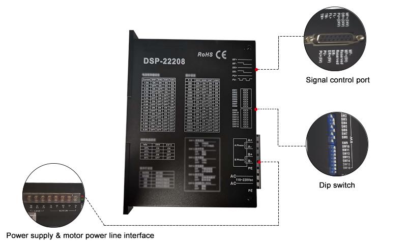
Function Description

PinFeatureOperation Instructions
PWRPower Indicator LightWhen powered on, the green light is on.
OCOver-current/ under-voltage/ over-voltage indicator lightCurrent is too high, voltage is too high or too low, the indicator light is on.
PU+Input signal photoelectric isolation positive terminalConnect the signal power 5V-24V can drive.
PU-SW15=OFF, it is the reverse step pulse signal
SW15=ON, it is the forward step pulse signal
The falling edge is valid, and the motor takes one step each time when pulse goes from high to low. Requirements: low level 0-0.5V, high level 4-5V, pulse width> 2.5μs.
DR+Input signal photoelectric isolation positive terminalConnect the signal power 5V-24V can drive.
DR-SW15=OFF is the forward step pulse signal
SW15=ON is the reverse stepping pulse signal
The falling edge is valid, and the motor takes one step each time when pulse goes from high to low. Requirements: low level 0-0.5V, high level 4-5V, pulse width> 2.5μs.
MF+Input signal photoelectric isolation positive terminalConnect the signal power 5V-24V can drive.
MF-Motor release signalWhen the motor coil current is switched off, the motor is free.
FL+Over-current/ under-voltage/ over-voltage photoelectric isolation positive terminalFL + connect to the output current limiting resistor.
FL-Over-current/ under-voltage/ over-voltage photoelectric isolation negative terminalFL- connect to the output, the maximum drive current of 50mA, the maximum voltage of 50V.
TM+Origin outputs photoelectric isolation positive terminalTM + connect to the output current limiting resistor.
TM-Origin outputs photoelectric isolation negative terminalTM- connect to the output, the maximum drive current of 50mA, the maximum voltage of 50V.
ACPowerAC 110-220V
Note: The default input signal is 5V pulse signal. When 24V input signal is required, please in series with1.8-2kΩ resistance.
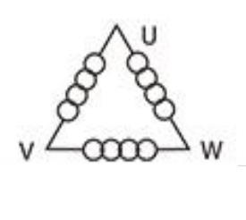
UMotor WiringDSP32207 wiring
V
W

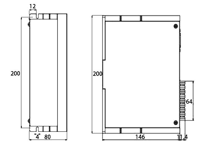
 Installation Size
DSP32207 size

Details

80v~220v Digital Stepper Driver Details
Tips: Drive circuit of stepper motors
Unipolar and bipolar driver architectures are most commonly used for stepper motors.
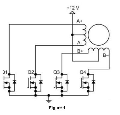
The unipolar drive circuit uses four transistors to drive two phases of the stepper motor. The motor configuration, as shown in Figure 1, consists of two sets of coils with center tap, and the entire motor has a total of six lines connected to the outside. Although the six-wire stepper motor is also known as unipolar stepper motor, it can actually use unipolar or bipolar drive circuit at the same time.
unipolar circuitThe drive circuit of a bipolar stepper motor is shown in Figure 2, which uses eight transistors to drive two phases. Bipolar drive circuit can also drive a four-wire or six-wire stepper motor. Although it can only use bipolar drive circuit, a four-wire motor can significantly reduce the cost of mass-production applications. The number of transistors used in drive circuits of bipolar stepper motors is twice that of transistors used in a unipolar drive circuit, in which four lower transistors are usually driven directly by a microcontroller while the upper transistor requires an upper driver circuit of higher cost.
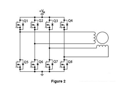
Bipolar circuit

Transistors used in bipolar drive circuits only need to withstand motor voltage. Therefore, they do not need to clamp the same circuit as unipolar drive circuits do.

How to control a stepper motor using a PLC and HMI?
This video shows you how to configure a PLC, HMI, motor driver, and proximity sensor to perform Origin Return (OPR) control of a stepper motor.

Common Stepper Motor Troubleshooting Problems and Tips
In this video, 9 common problems that can occur with stepper motors are discussed, and expert advice is provided for diagnosing and effectively resolving these problems. If you have ever experienced problems with your stepper motor or want to be prepared for any future problems, this video is a must watch.

Product reviews
Good stepper motor driver at an affordable price!
5
Jose
Avatar
3/29/2022 9:19 PM
As advertised and fast shipping,  all seem well packaged and in great shape. Easy install, product as described. I bought this stepper motor driver to replace my old one and everything goes great.
Was this review helpful? Yes No (0/0)
Reliable stepper motor driver
5
Maren
Avatar
7/15/2026 7:13 PM
We use this motor driver on our packaging line indexing station. The 3‑phase drive is smooth, and the 30000 steps/rev gives precise positioning. Runs cool all day. Good value.
Was this review helpful? Yes No (0/0)
Write your review
  • Only registered users can write reviews
*
*
  • Bad
  • Excellent
*
*
*
*

3-phase digital stepper driver, AC 100V-220V power supply, maximum output current 7A/ phase, 30000 steps/ turn of the 16 subdivision mode optional, suitable for 3 phase Nema 34, 42 stepper motor, manufacturer direct sale.

Function Description

PinFeatureOperation Instructions
PWRPower Indicator LightWhen powered on, the green light is on.
OCOver-current/ under-voltage/ over-voltage indicator lightCurrent is too high, voltage is too high or too low, the indicator light is on.
PU+Input signal photoelectric isolation positive terminalConnect the signal power 5V-24V can drive.
PU-SW15=OFF, it is the reverse step pulse signal
SW15=ON, it is the forward step pulse signal
The falling edge is valid, and the motor takes one step each time when pulse goes from high to low. Requirements: low level 0-0.5V, high level 4-5V, pulse width> 2.5μs.
DR+Input signal photoelectric isolation positive terminalConnect the signal power 5V-24V can drive.
DR-SW15=OFF is the forward step pulse signal
SW15=ON is the reverse stepping pulse signal
The falling edge is valid, and the motor takes one step each time when pulse goes from high to low. Requirements: low level 0-0.5V, high level 4-5V, pulse width> 2.5μs.
MF+Input signal photoelectric isolation positive terminalConnect the signal power 5V-24V can drive.
MF-Motor release signalWhen the motor coil current is switched off, the motor is free.
FL+Over-current/ under-voltage/ over-voltage photoelectric isolation positive terminalFL + connect to the output current limiting resistor.
FL-Over-current/ under-voltage/ over-voltage photoelectric isolation negative terminalFL- connect to the output, the maximum drive current of 50mA, the maximum voltage of 50V.
TM+Origin outputs photoelectric isolation positive terminalTM + connect to the output current limiting resistor.
TM-Origin outputs photoelectric isolation negative terminalTM- connect to the output, the maximum drive current of 50mA, the maximum voltage of 50V.
ACPowerAC 110-220V
Note: The default input signal is 5V pulse signal. When 24V input signal is required, please in series with1.8-2kΩ resistance.
UMotor WiringDSP32207 wiring
V
W

 Installation Size
DSP32207 size

Details

80v~220v Digital Stepper Driver Details
Tips: Drive circuit of stepper motors
Unipolar and bipolar driver architectures are most commonly used for stepper motors.
The unipolar drive circuit uses four transistors to drive two phases of the stepper motor. The motor configuration, as shown in Figure 1, consists of two sets of coils with center tap, and the entire motor has a total of six lines connected to the outside. Although the six-wire stepper motor is also known as unipolar stepper motor, it can actually use unipolar or bipolar drive circuit at the same time.
unipolar circuitThe drive circuit of a bipolar stepper motor is shown in Figure 2, which uses eight transistors to drive two phases. Bipolar drive circuit can also drive a four-wire or six-wire stepper motor. Although it can only use bipolar drive circuit, a four-wire motor can significantly reduce the cost of mass-production applications. The number of transistors used in drive circuits of bipolar stepper motors is twice that of transistors used in a unipolar drive circuit, in which four lower transistors are usually driven directly by a microcontroller while the upper transistor requires an upper driver circuit of higher cost.

Bipolar circuit

Transistors used in bipolar drive circuits only need to withstand motor voltage. Therefore, they do not need to clamp the same circuit as unipolar drive circuits do.

Product reviews
Good stepper motor driver at an affordable price!
5
Jose
Avatar
3/29/2022 9:19 PM
As advertised and fast shipping,  all seem well packaged and in great shape. Easy install, product as described. I bought this stepper motor driver to replace my old one and everything goes great.
Was this review helpful? Yes No (0/0)
Reliable stepper motor driver
5
Maren
Avatar
7/15/2026 7:13 PM
We use this motor driver on our packaging line indexing station. The 3‑phase drive is smooth, and the 30000 steps/rev gives precise positioning. Runs cool all day. Good value.
Was this review helpful? Yes No (0/0)
Only registered users can write reviews