
The asymmetric cycler time delay relay is an electrical control device that can be easily installed on a DIN rail. It has an LED light to display the device status and has a 10-position delay range to choose from. It automatically detects faults and can quickly cut off the power supply to the faulty part to prevent the expansion of the fault. It improves the reliability and stability of the power system and reduces the workload of operators.
Feature
- 2 time functions:
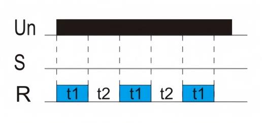
- Cycler beginning with pulse
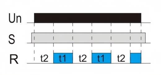
- Cycler beginning with pause
- Function choice is done by an external jumper of terminals S-A1.
- Time scale 0.1 s - 100 days divided into 10-time ranges: (0.1 s - 1 s/ 1 s - 10 s/ 0.1 min - 1 min/ 1 min - 10 min/ 0.1 hrs - 1 h/ 1 hrs - 10 hrs/ 0.1 day - 1 day/ 1 day - 10 days/ 3 days - 30 days/ 10 days - 100 days).
- Relay status is indicated by LED.
- 1-MODULE, DIN rail mounting.
Mode and Connotation
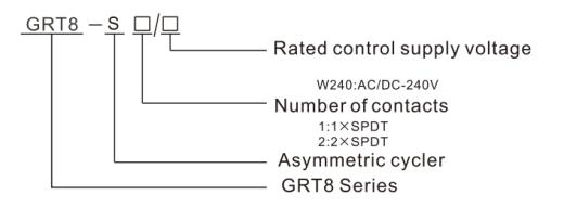
Technical Parameters
| Model | ATO-GRT8-S1 | ATO-GRT8-S2 |
| Function | Asymmetric cycler time relay | |
| Supply Terminals | A1-A2 | |
| Voltage Range | AC/DC 12V-240V (50-60Hz) | |
| Burden | AC 0.09-3VA/ DC 0.05-1.7W | |
| Supply Voltage Tolerance | -15%;+10% | |
| Supply Indication | Green LED | |
| Time Ranges | 0.1 s - 10 days | |
| Time Setting | Potentiometer | |
| Time Deviation | 10% - mechanical setting | |
| Repeat Accuracy | 0.2% - set value stability | |
| Temperature Coefficient | 0.05%/°C, at=20°C (0.05%°F,at=68°F) | |
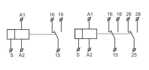
| Output | 1×SPDT | 2×SPDT |
| Current Rating | 1×16A (AC1) | 2×16A (AC1) |
| Switching Voltage | 250VAC/24VDC | |
| Min. breaking Capacity DC | 500mW | |
| Output Indication | Red LED | |
| Mechanical Life | 1×10⁷ | |
| Electrical Life (AC1) | 1×10⁵ | |
| Reset Time | Max. 200ms | |
| Operating Temperature | -20°℃ to +55℃ (-4F to 131°F) | |
| Storage Temperature | -35°℃ to +75°℃ (-22°F to 158°F) | |
| Mounting/ DIN Rail | Din rail EN/ IEC 60715 | |
| Protection Degree | IP40 for front panel/ IP20 terminals | |
| Operating Position | Any | |
| Overvoltage Cathegory | III. | |
| Pollution Degree | 2 | |
| Max. cable Size (mm2 ) | Solid wire max. 1×2.5 or 2×1.5/ with sleeve max. 1×2.5 (AWG 12) | |
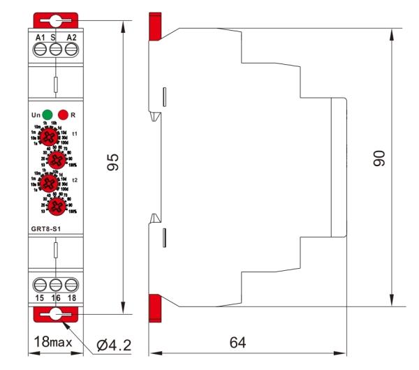
| Dimensions | 90mm×18mm×64mm | |
| Weight | 1×SPDT: 62g 2×SPDT: 82g | |
| Standards | EN61812-1, IEC60947-5-1 | |
Wiring Diagram
Functions Diagram
- Cycler beginning with pulse
- Cycler beginning with pause (jumper A1-S)
Dimensions (mm)
Tips: In terms of working principle, the asymmetric cycler timer relay can achieve the following functions
- Through the preset action time and release time, the circuit can be timed and controlled, such as turning on or off certain equipment at a specific time every day.
- When a fault occurs in the power system, the relay can act according to the predetermined program, cut off the fault circuit, and protect the safety of the equipment and system.
- In some application scenarios, the equipment may need to work intermittently to prevent overheating or other potential problems. The relay can perform switching operations within the set time interval.
- The relay can control the circuit according to the set cycle mode, such as repeatedly opening and closing.
Only registered users can write reviews
Customers who bought this item also bought

Brushed DC Motor with Gearbox, 2800rpm, 12V/24V, 32mm
ATO-BDM-2800R32
$135.36
Favorable price 6.5W/7W Brushed DC motor for sale, 12V or 24V, 2800rpm rated speed, 3500rpm no load speed, comes with 32mm diameter gearbox, gear ratio from 1/3.7 to 1/139 to provide different rated speed and torque.
Related products

Programmable Timer Relay, 12-Input 12-Output, 24V DC
ATO-TIMER-24PLC
$156.77
Brand new programmable timer relay, works as both multiple timer relays and a simple PLC controller for independent control and high accuracy, 12-in and 12-out relay output, compatible with PNP/NPN switching signal. Optional analog input/output 0~20mA, 0~10V, 485 Modbus. 24V DC power supply, easy-to-read LCD display, convenient DIN rail mounting, easy to operate, high performance and affordable price.

Programmable Timer Relay, 16-Input 16-Output, 24V DC
ATO-TIMER-32PLC
$184.62
This 16-input 16-output programmable timer relay, aka. simple PLC controller, can replace both multiple timer relays and ordinary PLC, with more powerful & accurate timing function and easy to learn & understand programming. This simple PLC controller is relay type with power supply 24V DC. The input is compatible with PNP/NPN switching signal. Optional analog input/output 0~20mA, 0~10V, 485 Modbus. Easy to use and favorable price.

Time Delay Relay, Double Delay On, AC 220V, AC/DC 12-240V
ATO-TIMER-GRT82T
$63.46
Double Delay Time Delay Relay, equipped to handle a wide input voltage range, accepting AC 220V as well as AC/DC 12-240V inputs. Operating seamlessly in temperatures spanning from -20°C to 55°C, it ensures reliable performance across varying environmental conditions. This timer relay features two independent delay control circuits, allowing you to flexibly control two different time delays to meet diverse application needs.

Asymmetric Cycler Timer Relay, SPDT, AC/DC 12V-240V
ATO-TIMER-GRT8S
$64.32
The asymmetric cycler time delay relay has 1×SPDT/ 2×SPDT these two output types. It has a separate delay setting function and can be set in an ultra-wide delay range of 0.1 seconds to 100 days, which can automatically switch the circuit opening and closing state in two different time intervals to achieve intermittent operation of the equipment. In addition, by short-circuiting S-A1, different working modes can be switched. Timed or intermittent fine control and protection of equipment in the power system can be achieved.