
Good price inductive proximity sensor with rated range 5mm/ 8mm, reverse polarity protection loop protection. Analog inductive sensor is widely used in displacement measurement, thickness measurement, material differentiation and other fields.
Specification
| Model | ATO-LR18X | |
| Installation type | Flush | Non-flush |
| Rated distance | 5mm | 8mm |
| Detection range | 1-5mm | 1.6-8mm |
| Switching frequency | 200 Hz | 100 Hz |
| Analog signal output | 0-10V/ 0-20mA/ 4-20mA/ 0-10V+0-20mA | |
| Diameter | M18 | |
| Connection type | M12 connector/ 2m PVC cable | |
| Supply Voltage | 15-30VDC | |
| Standard target | Fe 18*18*1t | Fe 24*24*1t |
| Switch-point drifts | ≤±10%/ Sr | |
| Linearity | ≤±5% | |
| Repeat accuracy | ≤±3% | |
| Load current | ≥4.7KΩ (voltage output) ≤470Ω (current output) | |
| Current consumption | ≤20mA | |
| Loop protection | Reverse polarity protection | |
| Power indicator | Yellow LED | |
| Ambient temperature | -25℃-70℃ | |
| Ambient humidity | 35-95% RH | |
| Voltage withstand | 1000V/ AC 50/ 60Hz 60s | |
| Insulation resistance | ≥50MΩ (500VDC) | |
| Vibration resistant | Complex amplitude 1.5mm 10-50Hz (X, Y, Z directions for 2 hours each) | |
| Protection class | IP67 | |
| Housing material | Nickel-copper alloy | |
| Certificates | CE, UL,CCC, ROHS | |
| Warranty | 12 months | |
Dimension (unit: mm)
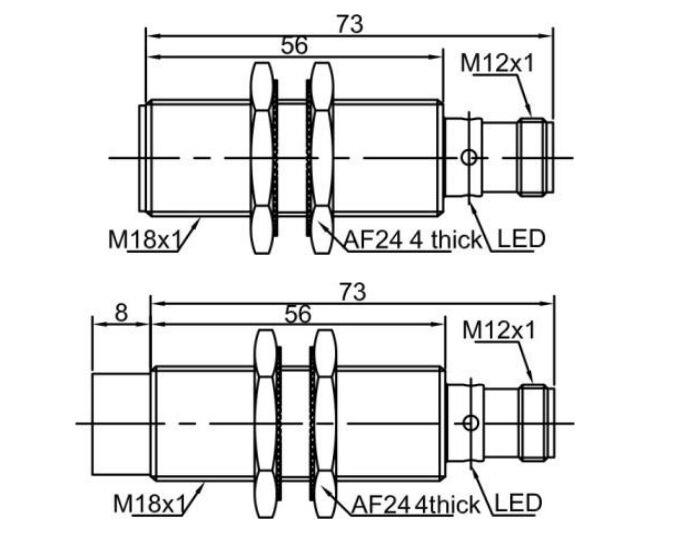
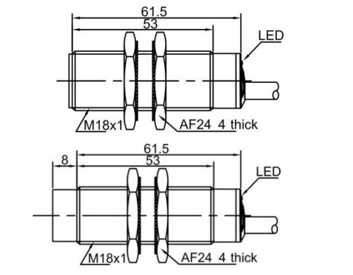
Wiring diagram
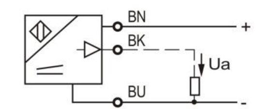
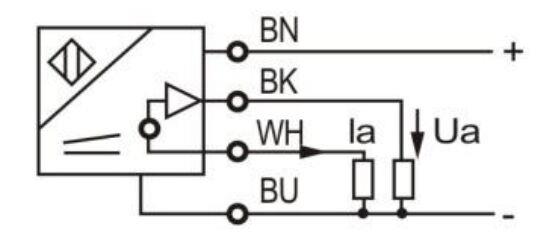
0-10V 0-10V+ 0-20mA
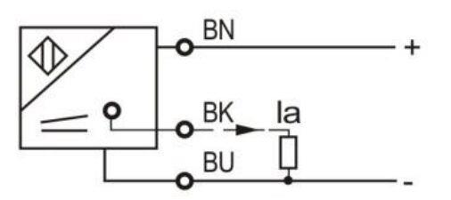
0-20mA/ 4-20mA
Tips: Installation precautions for analog output inductive proximity sensors
When installing analog output inductive proximity sensors, you should choose the appropriate installation method (flush or non-flush) according to the model to avoid errors or unstable detection due to metal interference. Flush-mounted sensors need to be completely embedded in the metal surface and are suitable for environments with compact space and less interference; non-flush-mounted sensors need to maintain a certain gap and are suitable for occasions where the detection distance is required to be greater.
In addition, to ensure signal stability, mutual interference between sensors should be avoided, and it is recommended to maintain the specified minimum installation spacing. Shielded cables should be used for wiring, and they should be kept away from strong power lines or variable frequency drives and other frequency conversion devices to prevent analog signals from being interfered with. After installation, the output curve should be confirmed to match the target distance through debugging to ensure the accuracy and reliability of system operation.


Analog Output Inductive Proximity Sensor, Cylindrical, 0-10V/4-20mA

Analog Output Proximity Sensor, Inductive, Flush/ Non-flush, IP67

Analog Output Proximity Sensor, Inductive, Flush/Non-flush, M12

Analog Output Proximity Sensor, Inductive, M12 Connector/ Terminal Connection
