40 Amps Isolator Switch, 3 Pole/ 4 Pole

$82.89
3 Pole isolator switch rated current 40 amps, rated insulation voltage 690V, small size and light weight, cheap price and perfect quality. It’s widely used in the distribution system and automatic system of architecture, electrical power, petrochemical, and other industries.
SKU: ATO-IS-HGL40A
*
*
Free Shipping
Delivery date: 6-12 days

Low cost disconnect switch rate with 40A, 3 pole or 4 pole to choose from, dielectric strength 5000V, rated insulation voltage 690V. Compact size easy connection, high performance and long electrical life.

40 Amp Isolator Switch Specification

BasicsModelATOHGL-40A
Pole3 Pole/4 Pole
Weight3 Pole0.40 kg
4 Pole0.42 kg
Technical ParametersRated current40A
Rated insulation voltage Ui690V
Dielectric strength1890V
Rated surge-resistant voltage Uimp kV (installed category IV)8
Rated working current le380VAC-2140A
AC-2240A
AC-2340A
660VAC-2140A
AC-2232A
DC-2325A
220VDC-2121A
DC-2240A
DC-2340A
Motor power P (380V) kW380V160 kW
660V185 kW
Rated short-time withstand current lcw (kA rms) 0.1s/ 1.0s2
Rated breaking capability Icn (Arms) AC23 380VA320
Rated making capacity Icm (Arms) AC23 380V400
Rated short-current making capacity Icm' (Kapeak value)7.5
Mechanical durability (number of cyclic operation)10000
Electric durability Ue=660V, Rated currentCOSφ=0.65AC221700
COSφ=0.35AC23100
COSφ=0.95AC21500
Working EnvironmentMoment of operation1.2 Nm
Temperature-5℃~+55℃
Way of workingContinuously working
OperatingHandle
Installation formVertical
Altitude≤2000m
Pollution level3
Overvoltage levelⅢ
IP levelIP 20

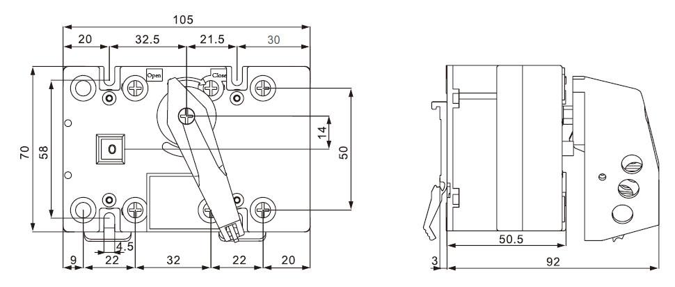
Dimension

63A isolator switch dimension

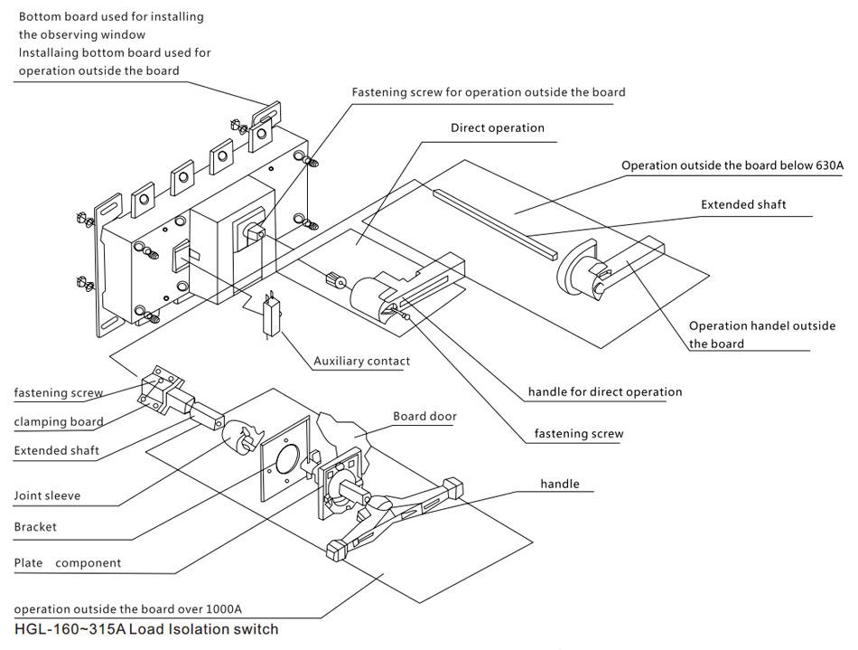
Operation Mode

Load Isolator Disconnect Switch

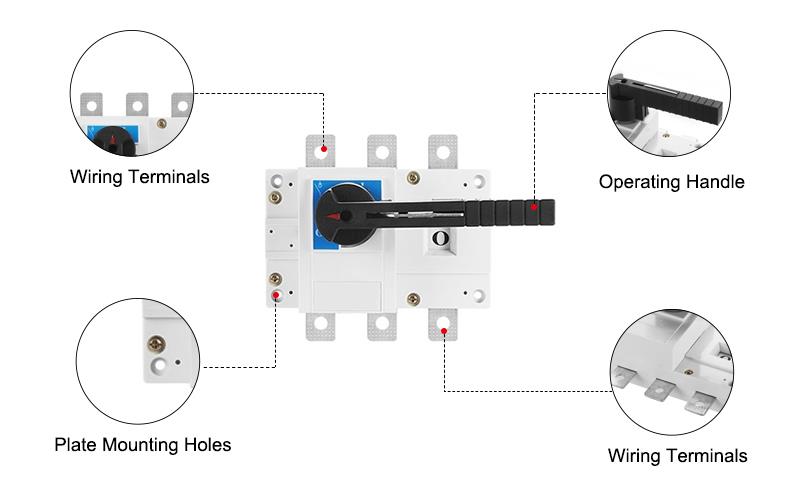
Details

40 Amps Isolator Switch Details

Tips: How to use an isolating switch?

1. When operating the isolating switch, first check that the circuit breaker of the corresponding circuit is indeed in the off position to prevent the isolating switch from being pulled and closed with load.
2. When the line is stopped and the power is transmitted, the isolation switch must be opened and closed in order. During power outage operation, the circuit breaker must be pulled first, then the line side isolating switch, and then the bus side isolating switch. The sequence of power transmission operation is opposite to that of power failure. This is because in the event of misoperation, the scope of the accident can be reduced in the above order to avoid man-made accidents from expanding to the bus.
3. During operation, if serious defects such as serious damage to the insulator or the transmission rod of the isolating switch are found, no operation is allowed.
4. During the operation of the isolating switch, there should be personnel on duty to check the opening and closing positions, synchronization conditions, contact depth and other items phase by phase at the scene to ensure that the isolating switch has the correct action and position.
5. The isolation switch should generally be operated in the main control room. When the remote control electrical operation fails, manual or electric operation can be carried out on-site, but the permission of the station master or technical person in charge must be obtained and the operation can be carried out under the condition of on-site supervision.
6. Electrical, electromagnetic and mechanical locking devices to prevent misoperation are installed between the isolating switch, the grounding switch and the circuit breaker. When the switching operation is performed, it must be carried out in sequence. If the locking device fails or the isolating switch and the grounding switch cannot operate normally, the position status of the corresponding circuit breaker and switch must be checked strictly according to the requirements of the lock. Only after the correctness is checked, the lock can be released for operation.

Load Break Switches Explained

In this video, we delve into the world of load break switches, mechanical devices capable of being operated while under load. We'll explore their functionality, applications in electrical systems, and provide a detailed breakdown of their features to equip you with a thorough comprehension of their advantages.

Different Types of Isolators and Their Uses

This video explains the popular types of switch isolators on the market and their potential applications in everyday and industrial use.

Product reviews
Isolator switch works great and seems sturdy!
5
Shake
Avatar
3/27/2022 7:07 PM
This isolator switch works great and seems extremely well built. If I ever need another I’d buy it again. Great price and easy to install. Excellent value and compact size. I highly recommend it!
Was this review helpful? Yes No (0/0)
Very reliable
5
Ross
Avatar
10/20/2025 9:02 PM
Compact, sturdy, and easy to wire. I used the 3-pole version for my small workshop setup. it operates smoothly and feels very reliable.
Was this review helpful? Yes No (0/0)
Write your review
  • Only registered users can write reviews
*
*
  • Bad
  • Excellent
*
*
*
*

Low cost disconnect switch rate with 40A, 3 pole or 4 pole to choose from, dielectric strength 5000V, rated insulation voltage 690V. Compact size easy connection, high performance and long electrical life.

40 Amp Isolator Switch Specification

BasicsModelATOHGL-40A
Pole3 Pole/4 Pole
Weight3 Pole0.40 kg
4 Pole0.42 kg
Technical ParametersRated current40A
Rated insulation voltage Ui690V
Dielectric strength1890V
Rated surge-resistant voltage Uimp kV (installed category IV)8
Rated working current le380VAC-2140A
AC-2240A
AC-2340A
660VAC-2140A
AC-2232A
DC-2325A
220VDC-2121A
DC-2240A
DC-2340A
Motor power P (380V) kW380V160 kW
660V185 kW
Rated short-time withstand current lcw (kA rms) 0.1s/ 1.0s2
Rated breaking capability Icn (Arms) AC23 380VA320
Rated making capacity Icm (Arms) AC23 380V400
Rated short-current making capacity Icm' (Kapeak value)7.5
Mechanical durability (number of cyclic operation)10000
Electric durability Ue=660V, Rated currentCOSφ=0.65AC221700
COSφ=0.35AC23100
COSφ=0.95AC21500
Working EnvironmentMoment of operation1.2 Nm
Temperature-5℃~+55℃
Way of workingContinuously working
OperatingHandle
Installation formVertical
Altitude≤2000m
Pollution level3
Overvoltage levelⅢ
IP levelIP 20

Dimension

63A isolator switch dimension

Operation Mode

Load Isolator Disconnect Switch

Details

40 Amps Isolator Switch Details

Tips: How to use an isolating switch?

1. When operating the isolating switch, first check that the circuit breaker of the corresponding circuit is indeed in the off position to prevent the isolating switch from being pulled and closed with load.
2. When the line is stopped and the power is transmitted, the isolation switch must be opened and closed in order. During power outage operation, the circuit breaker must be pulled first, then the line side isolating switch, and then the bus side isolating switch. The sequence of power transmission operation is opposite to that of power failure. This is because in the event of misoperation, the scope of the accident can be reduced in the above order to avoid man-made accidents from expanding to the bus.
3. During operation, if serious defects such as serious damage to the insulator or the transmission rod of the isolating switch are found, no operation is allowed.
4. During the operation of the isolating switch, there should be personnel on duty to check the opening and closing positions, synchronization conditions, contact depth and other items phase by phase at the scene to ensure that the isolating switch has the correct action and position.
5. The isolation switch should generally be operated in the main control room. When the remote control electrical operation fails, manual or electric operation can be carried out on-site, but the permission of the station master or technical person in charge must be obtained and the operation can be carried out under the condition of on-site supervision.
6. Electrical, electromagnetic and mechanical locking devices to prevent misoperation are installed between the isolating switch, the grounding switch and the circuit breaker. When the switching operation is performed, it must be carried out in sequence. If the locking device fails or the isolating switch and the grounding switch cannot operate normally, the position status of the corresponding circuit breaker and switch must be checked strictly according to the requirements of the lock. Only after the correctness is checked, the lock can be released for operation.

Product reviews
Isolator switch works great and seems sturdy!
5
Shake
Avatar
3/27/2022 7:07 PM
This isolator switch works great and seems extremely well built. If I ever need another I’d buy it again. Great price and easy to install. Excellent value and compact size. I highly recommend it!
Was this review helpful? Yes No (0/0)
Very reliable
5
Ross
Avatar
10/20/2025 9:02 PM
Compact, sturdy, and easy to wire. I used the 3-pole version for my small workshop setup. it operates smoothly and feels very reliable.
Was this review helpful? Yes No (0/0)
Only registered users can write reviews