
Nema 23 bipolar Stepper motor, 3A phase current, 1.2Nm in 56mm, 1.8 degree, 2phase 4 wires, manufacturer direct sale.
Specification
| Electrical Specification | Model | ATO57HS56-3004 |
| Matched Driver Model | ATODSP57(Click it to see more info) | |
| Step Angle | 1.8° | |
| Holding Torque | 1.2Nm | |
| Rated Current/phase | 3A | |
| Phase Resistance | 0.95Ω | |
| Inductance | 2.8mH | |
| Rotor Inertia | 300g-cm2 | |
| Physical Specification | Frame Size | 57 x 57mm |
| Length | 56mm | |
| Shaft Diameter | Φ8mm | |
| Shaft Length | 19mm | |
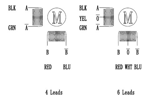
| Motor Leads | 4 | |
| Weight | 0.7kg | |
| Technical Parameters | Step Angle Accuracy | ±5% (full step, no load) |
| Resistance Accuracy | ±10% | |
| Inductance Accuracy | ±20% | |
| Temperature Rise | 80℃ Max. (rated current, 2 phase on) | |
| Ambient Temperature | -20℃~+50℃ | |
| Insulation Resistance | 100MΩ Min. 500VDC | |
| Dielectric Strength | 500V AC for one minute | |
| Shaft Radial Play | 0.02Max. 450g | |
| Shaft Axial Play | 0.08Max. 450g | |
| Quality Assurance | Warranty Period | 12 months |
| Certificate | CE, ROHs, ISO/SGS9001 |
Dimensions: (Unit=mm)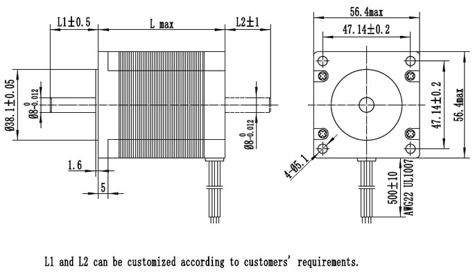
L Max=56mm, Shaft Length=L1-1.6mm, L1(Common)=20.6mm
Wiring Diagram
Tips: What should be checked before powering on the stepper motor?
- Check whether the power is proper (in case of overvoltage, the drive module may be damaged); the positive and negative polarity of DC input should not be wrong. Whether the motor type or current setting on the drive controller is proper (not too large at the very beginning).
- Control signal line is connected firmly and it’s better to give considerations into the problem about shielding (like using twisted-pair) at the industrial field.
- At the very beginning, do not directly connect all necessary lines but the most basic system, and then connect one by one after the motor rotates in good state.
- Be clear about earthing methods, or don’t connect it.
- Closely observe the state of motor within 30min after the motor rotates, like whether it rotates normally, as well as sound and temperature rise. If discovering the problem, please stop it and make adjustment.
Only registered users can write reviews
Related products

Nema 23 Stepper Motor Bipolar, 1.8 degree, 1.5A, 2 phase 4 wires
ATO-STEP-2622301
$69.15
Bipolar stepper motor Nema 23, 1.5A and 1.6 ohms, 2 phase 4 wires, 0.82 Nm holding torque, 1.8 deg. step angle, brand new and manufacturer direct sale.

Nema 23 Stepper Motor Bipolar, 1.8 degree, 2A, 2 phase 4 wires
ATO-STEP-2622302
$69.15
Nema 23 Bipolar stepper motor with 1.8 deg. step angle. Each phase draws current 2A, allowing for a holding torque of 0.9Nm. Reasonable price and manufacturer direct sale.

Nema 23 Stepper Motor Bipolar, 1.8 degree, 3A, 2 phase 4 wires
ATO-STEP-2622303
$69.15
Favorable price Nema 23 Bipolar stepper motor, 1.8 deg. step angle, 2 phase, allowing for a holding torque of 1.5Nm, manufacturer direct sale.

Nema 23 Stepper motor, 1A, 1.8 degree, 2 phase 6 wires
ATO-STEP-2412301
$63.31
Favorable price Nema 23 stepper motor, 0.9Nm holding torque, 1.8 deg. step angle, manufacturer direct sale.