Multifunction Time Delay Relay, AC 220V, AC/DC 12-240V

$56.32
Multifunction Time Delay Relay, a meticulously designed electrical control device crafted to meet a diverse array of time delay requirements. Supporting both AC 220V and AC/DC 12-240V power inputs, and accommodating frequencies of 50-60Hz, this timer relay offers compatibility with a wide range of electrical systems, ensuring enhanced flexibility and usability. Equipped with multiple functionalities, it is engineered to provide reliable control and flexible operation for your circuit systems.
SKU: ATO-TIMER-GRT8M
*
Free Shipping
Delivery date: 6-12 days

ATO Multifunction Time Delay Relay, a versatile electrical control device compatible with a wide range of power inputs, including AC 220V and AC/DC 12-240V. Its flexible operating modes and precise time control features make it suitable for various applications, from industrial automation to household use. Whether it's delay-on, delay-off, or cyclic delay, the multifunction timer relay provides precise control over circuit operations, making it an ideal choice for applications requiring accurate timing control, such as industrial automation, lighting systems, temperature regulation, motor control, and more.

Feature

  • The time delay relay offers 10 distinct functions, comprising five time functions regulated by the supply voltage, four time functions controlled by a control input, and one function featuring a latching relay mechanism.
  • Comfortable and well-arranged function and time-range setting by rotary switches.
  • Time scale 0.1s-10 days divided into 10 ranges.
  • Relay status is indicated by LED.
  • 1-MODULE, DIN rail mounting.

Specification

ModelATO-GRT8-M1
Supply terminalsA1-A2
Voltage rangeAC/DC 12-240V (50-60Hz)AC 220V (50-60Hz)
BurdenAC 0.09-3VA/DC 0.05-1.7W
Power inputAC max.6VA/1.3w
Supply voltage tolerance-15%; +10%
Supply indicationgreen LED
Time ranges0.1s-10 days, ON, OFF
Time settingpotentionmeter
Time deviation10%-mechanical setting
Repeat accuracy0.2%-set value stability
Temperature coefficient0.05%/°C, at=20°C (0.05%°F, at=68°F)
Output1×SPDT
Current rating1×16A (AC1)
Switching voltage250VAC/24VDC
Min.breaking capacity DC500mW
Output indicationred LED
Mechanical life1×107
Electrical life (AC1)1×10⁵
Reset timemax.200ms
Operating temperature-20℃ to +55°C (-4°F to 131°F)
Storage temperature-35°C to +75°C (-22°F to 158°F)
Mounting/DIN railDin rail EN/IEC 60715
Protection degreeIP40 for front panel/IP20 terminals
Operating altitude≤2000m
Operating positionany
Overvoltage cathegoryⅢ.
Pollution degree2
Max.cable size (mm2)solid wire max.1×2.5 or 2×1.5/with sleeve max.1×2.5 (AWG 12)
Dimensions90×18×64mm
WeightW240-62g, A220-60g
StandardsGB/T 14048.5, EN 61812-1, IEC 60947-5-1

Functions Diagram

A: On Delay (Power On)
When the input voltage U is applied, timing delay t begins. Relay contacts R change state after time delay is complete. Contacts R return to their shelf state when input voltage U is removed. Trigger switch is not used in this function.

Multifunction time delay relay functions diagram a

B: lnterval (Power On)
When input voltage U is applied, relay contacts R change state immediately and timing cycle begins. When time delay is complete, contacts return to shelf state. When input voltage U is removed, contacts will also return to their shelfstate. Trigger switch is not used in this function.

Multifunction time delay relay functions diagram b

C: Repeat Cycle (Starting Off)
When input voltage U is applied, time delay t begins. When time delay t is complete, relay contacts R change state for time delay t. This cycle will repeat until input voltage U is removed. Trigger switch is not used in this function.

Multifunction time delay relay functions diagram c

D: Repeat Cycle (Starting On)
When input voltage U is applied, relay contacts R change state immediately and time delay t begins. When time delay t is complete, contacts return to their shelf state for time delay t. This cycle will repeat until input voltage U is removed. Trigger switch is not used in this function.

Multifunction time delay relay functions diagram d

E: Off Delay (S Break)
Input voltage U must be applied continuously. When trigger switch S is closed, relay contacts R change state. When trigger switch S is opened, delay t begins. When delay t is complete, contacts R return to their shelf state. If trigger switch S is closed before time delay t is complete, then time is reset. When trigger switch S is opened, the delay begins again, and relay contacts R remain in their energized state. If input voltage u is removed, relay contacts R return to their shelf state.

Multifunction time delay relay functions diagram e

F: Single Shot
Upon application of input voltage U, the relay is ready to accept trigger signals. Upon application of the trigger signal S, the relay contacts R transfer and the preset time t begins. During time-out, the trigger signal S is ignored. The relay resets by applying the trigger switch S when the relay is not energized.

Multifunction time delay relay functions diagram f

G: Single Shot Trailing Edge (Non-Retriggerable)
Upon application of input voltage u, the relay is ready to accept trigger signals. Upon application of the trigger signal S, the relay contacts R transfer and the preset time t begins. At the end of the preset time t, the relay contacts R return to their normal condition unless the trigger switch S is opened and closed prior to time out t (before preset time elapses). Continuous cycling of the trigger switch S at a rate faster than the preset time will cause the relay contacts R to remain closed. If input voltage U is removed, relay contacts R return to their shelf state.

Multifunction time delay relay functions diagram g

H: On/Off Delay
Input voltage U must be applied continuously. When trigger switch S is closed, time delay t begins. When time delay t is complete, relay contacts R change state and remain transferred until trigger switch S is opened. If input voltage U is removed, relay contacts R return to their shelf state.

Multifunction time delay relay functions diagram h

I: Latching Relay
Input voltage U must be applied continuously. Output changes state with every trigger switch S closure. If input voltage U is removed, relay contacts R return to their shelf state.

Multifunction time delay relay functions diagram i

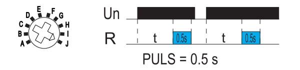
J: Pulse Generator
Upon application of input voltage U, a single output pulse of 0.5 seconds is delivered to relay after time delay t. Power must be removed and reapplied to repeat pulse. Trigger switch is not used in this function.
Multifunction time delay relay functions diagram j

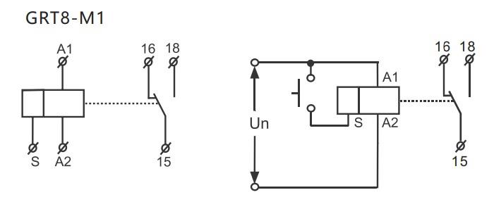
Wiring Diagram

Multifunction time delay relay wiring diagram

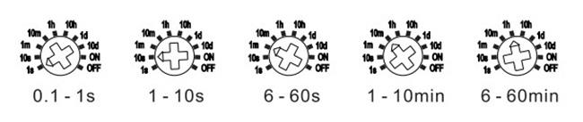
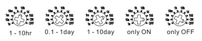
Time Range

Multifunction time delay relay time range1 diagram

Multifunction time delay relay time range2 diagram

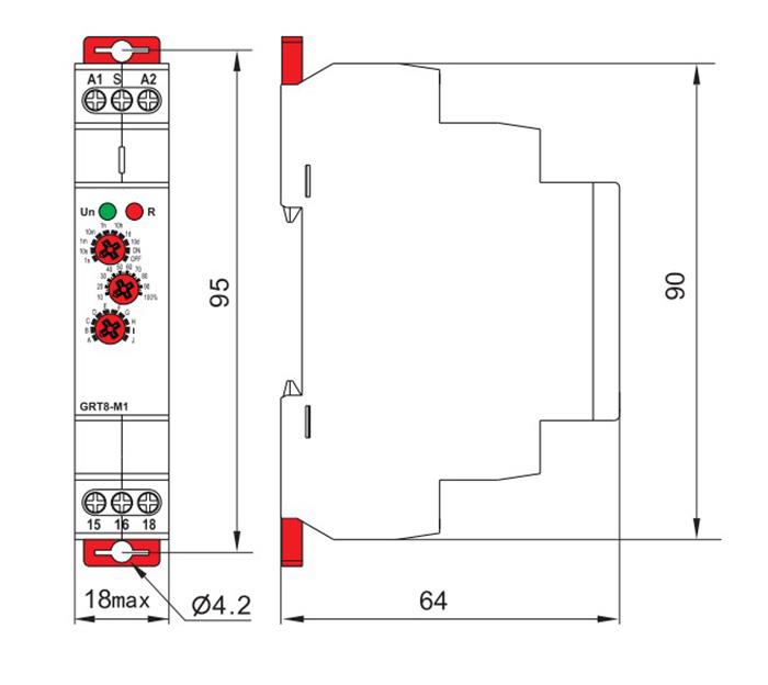
Dimensions (mm)

Multifunction time delay relay dimensions diagram

Tips: The Application of Multifunction Time Delay Relay

    • Industrial automation: Used for controlling the timing of machinery operations, such as delay-start or delay-stop functions, to optimize production processes.
    • Lighting systems control: Employed to implement time-delayed switching for lighting fixtures, helping to save energy and manage lighting schedules effectively.
    • Temperature control: Integrated into systems requiring precise timing for temperature regulation, ensuring equipment operates within optimal temperature ranges.
    • Motor control: Utilized in motor control applications to introduce time delays for motor start-up or shut-down sequences, preventing sudden power surges or overloads.
    • Home automation systems: Integrated with smart home setups to schedule automated tasks such as turning appliances on or off after a specific delay, enhancing convenience and energy efficiency.
    • Power equipment control: Applied in controlling the timing of power equipment operations, such as generators or pumps, to manage power distribution efficiently.
    • Security systems: Incorporated into security systems to introduce time delays for unlocking doors or activating alarms, enhancing security measures.

Product reviews
Set the running time of the pump
5
Leodis
Avatar
10/28/2024 12:12 AM
I want to stop a pump if it is running for more than a set time (single phase 240V).
Was this review helpful? Yes No (0/0)
ATO Responded
If you want to stop a pump if it is running for more than a set time, you can use this time delay relay ATO-TIMER-GRT8M to control the contactor coil of the pump. Connect the start contactor coil of the pump in series to the normally closed contact NC (15-16 terminals) of the time relay, and once the set time is reached, the relay will disconnect the coil of the contactor.
Write your review
  • Only registered users can write reviews
*
*
  • Bad
  • Excellent
*
*
*
*

ATO Multifunction Time Delay Relay, a versatile electrical control device compatible with a wide range of power inputs, including AC 220V and AC/DC 12-240V. Its flexible operating modes and precise time control features make it suitable for various applications, from industrial automation to household use. Whether it's delay-on, delay-off, or cyclic delay, the multifunction timer relay provides precise control over circuit operations, making it an ideal choice for applications requiring accurate timing control, such as industrial automation, lighting systems, temperature regulation, motor control, and more.

Feature

  • The time delay relay offers 10 distinct functions, comprising five time functions regulated by the supply voltage, four time functions controlled by a control input, and one function featuring a latching relay mechanism.
  • Comfortable and well-arranged function and time-range setting by rotary switches.
  • Time scale 0.1s-10 days divided into 10 ranges.
  • Relay status is indicated by LED.
  • 1-MODULE, DIN rail mounting.

Specification

ModelATO-GRT8-M1
Supply terminalsA1-A2
Voltage rangeAC/DC 12-240V (50-60Hz)AC 220V (50-60Hz)
BurdenAC 0.09-3VA/DC 0.05-1.7W
Power inputAC max.6VA/1.3w
Supply voltage tolerance-15%; +10%
Supply indicationgreen LED
Time ranges0.1s-10 days, ON, OFF
Time settingpotentionmeter
Time deviation10%-mechanical setting
Repeat accuracy0.2%-set value stability
Temperature coefficient0.05%/°C, at=20°C (0.05%°F, at=68°F)
Output1×SPDT
Current rating1×16A (AC1)
Switching voltage250VAC/24VDC
Min.breaking capacity DC500mW
Output indicationred LED
Mechanical life1×107
Electrical life (AC1)1×10⁵
Reset timemax.200ms
Operating temperature-20℃ to +55°C (-4°F to 131°F)
Storage temperature-35°C to +75°C (-22°F to 158°F)
Mounting/DIN railDin rail EN/IEC 60715
Protection degreeIP40 for front panel/IP20 terminals
Operating altitude≤2000m
Operating positionany
Overvoltage cathegoryⅢ.
Pollution degree2
Max.cable size (mm2)solid wire max.1×2.5 or 2×1.5/with sleeve max.1×2.5 (AWG 12)
Dimensions90×18×64mm
WeightW240-62g, A220-60g
StandardsGB/T 14048.5, EN 61812-1, IEC 60947-5-1

Functions Diagram

A: On Delay (Power On)
When the input voltage U is applied, timing delay t begins. Relay contacts R change state after time delay is complete. Contacts R return to their shelf state when input voltage U is removed. Trigger switch is not used in this function.

Multifunction time delay relay functions diagram a

B: lnterval (Power On)
When input voltage U is applied, relay contacts R change state immediately and timing cycle begins. When time delay is complete, contacts return to shelf state. When input voltage U is removed, contacts will also return to their shelfstate. Trigger switch is not used in this function.

Multifunction time delay relay functions diagram b

C: Repeat Cycle (Starting Off)
When input voltage U is applied, time delay t begins. When time delay t is complete, relay contacts R change state for time delay t. This cycle will repeat until input voltage U is removed. Trigger switch is not used in this function.

Multifunction time delay relay functions diagram c

D: Repeat Cycle (Starting On)
When input voltage U is applied, relay contacts R change state immediately and time delay t begins. When time delay t is complete, contacts return to their shelf state for time delay t. This cycle will repeat until input voltage U is removed. Trigger switch is not used in this function.

Multifunction time delay relay functions diagram d

E: Off Delay (S Break)
Input voltage U must be applied continuously. When trigger switch S is closed, relay contacts R change state. When trigger switch S is opened, delay t begins. When delay t is complete, contacts R return to their shelf state. If trigger switch S is closed before time delay t is complete, then time is reset. When trigger switch S is opened, the delay begins again, and relay contacts R remain in their energized state. If input voltage u is removed, relay contacts R return to their shelf state.

Multifunction time delay relay functions diagram e

F: Single Shot
Upon application of input voltage U, the relay is ready to accept trigger signals. Upon application of the trigger signal S, the relay contacts R transfer and the preset time t begins. During time-out, the trigger signal S is ignored. The relay resets by applying the trigger switch S when the relay is not energized.

Multifunction time delay relay functions diagram f

G: Single Shot Trailing Edge (Non-Retriggerable)
Upon application of input voltage u, the relay is ready to accept trigger signals. Upon application of the trigger signal S, the relay contacts R transfer and the preset time t begins. At the end of the preset time t, the relay contacts R return to their normal condition unless the trigger switch S is opened and closed prior to time out t (before preset time elapses). Continuous cycling of the trigger switch S at a rate faster than the preset time will cause the relay contacts R to remain closed. If input voltage U is removed, relay contacts R return to their shelf state.

Multifunction time delay relay functions diagram g

H: On/Off Delay
Input voltage U must be applied continuously. When trigger switch S is closed, time delay t begins. When time delay t is complete, relay contacts R change state and remain transferred until trigger switch S is opened. If input voltage U is removed, relay contacts R return to their shelf state.

Multifunction time delay relay functions diagram h

I: Latching Relay
Input voltage U must be applied continuously. Output changes state with every trigger switch S closure. If input voltage U is removed, relay contacts R return to their shelf state.

Multifunction time delay relay functions diagram i

J: Pulse Generator
Upon application of input voltage U, a single output pulse of 0.5 seconds is delivered to relay after time delay t. Power must be removed and reapplied to repeat pulse. Trigger switch is not used in this function.

Multifunction time delay relay functions diagram j

Wiring Diagram

Multifunction time delay relay wiring diagram

Time Range

Multifunction time delay relay time range1 diagram

Multifunction time delay relay time range2 diagram

Dimensions (mm)

Multifunction time delay relay dimensions diagram

Tips: The Application of Multifunction Time Delay Relay

    • Industrial automation: Used for controlling the timing of machinery operations, such as delay-start or delay-stop functions, to optimize production processes.
    • Lighting systems control: Employed to implement time-delayed switching for lighting fixtures, helping to save energy and manage lighting schedules effectively.
    • Temperature control: Integrated into systems requiring precise timing for temperature regulation, ensuring equipment operates within optimal temperature ranges.
    • Motor control: Utilized in motor control applications to introduce time delays for motor start-up or shut-down sequences, preventing sudden power surges or overloads.
    • Home automation systems: Integrated with smart home setups to schedule automated tasks such as turning appliances on or off after a specific delay, enhancing convenience and energy efficiency.
    • Power equipment control: Applied in controlling the timing of power equipment operations, such as generators or pumps, to manage power distribution efficiently.
    • Security systems: Incorporated into security systems to introduce time delays for unlocking doors or activating alarms, enhancing security measures.
Product reviews
Set the running time of the pump
5
Leodis
Avatar
10/28/2024 12:12 AM
I want to stop a pump if it is running for more than a set time (single phase 240V).
Was this review helpful? Yes No (0/0)
ATO Responded
If you want to stop a pump if it is running for more than a set time, you can use this time delay relay ATO-TIMER-GRT8M to control the contactor coil of the pump. Connect the start contactor coil of the pump in series to the normally closed contact NC (15-16 terminals) of the time relay, and once the set time is reached, the relay will disconnect the coil of the contactor.
Only registered users can write reviews