
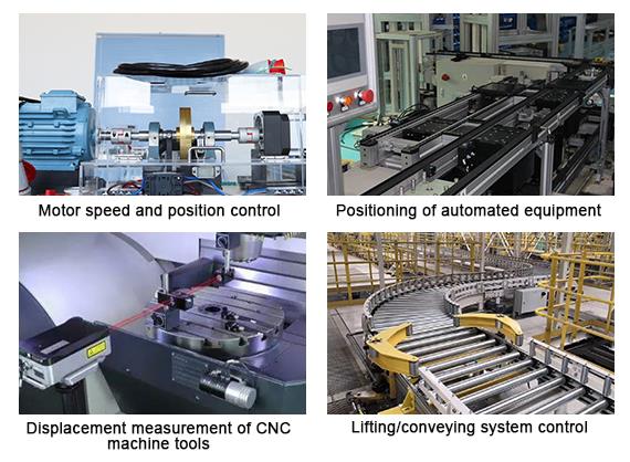
Incremental optical rotary encoders with 400 ppr can be used for robots, workbenches, injection molding machines, electronic equipment, printing and packaging machinery, non-standard equipment and CNC machine, a variety of office automation systems, industrial automation control and measurement fields.
Specification
| Basics | Model | ATO-S3806G-400BM | |||||||||||||||||||
| Weight | 100g | ||||||||||||||||||||
| Wiring | Color | Red | Black | Green | White | Yellow | Brown | Gray | Orange | ||||||||||||
| Signal | Vcc | GND | A | B | Z | A- | B- | Z- | |||||||||||||
| Mechanical properties | Maximum shaft speed (r/min) | 5000 | |||||||||||||||||||
| Starting torque | <0.03Nm (25℃) | ||||||||||||||||||||
| Maximum shaft load | Radial load: 50N, axial load: 20N | ||||||||||||||||||||
| Shock resistance | 50G/11ms | ||||||||||||||||||||
| Anti-vibration | 10G (10~2000Hz) | ||||||||||||||||||||
| Rotational inertia | 4X10⁻⁸kgm2 | ||||||||||||||||||||
| Operating temperature | -30~+85℃ (-22~+185℉) | ||||||||||||||||||||
| Storage temperature | -35~+95℃ (-31~+203℉) | ||||||||||||||||||||
| Protection Level | IP51 | ||||||||||||||||||||
| Electrical characteristics | Output circuit | Open-collector output | Voltage output | Push-pull output | Line driver output | ||||||||||||||||
| Supply voltage Vcc | DC 5V±0.2 | DC 5~24V | DC 5V±0.2 | DC 5~24V | DC 5V±0.2 | DC 5~24V | DC5V±0.2 | DC 5~24V | |||||||||||||
| Current consumption | ≤60mA | ≤60mA | ≤60mA | ≤100mA | |||||||||||||||||
| Output high level | ≥3.5V | ≥Vcc-2.5V | - | - | ≥2.5V | ≥Vcc-2.5V | |||||||||||||||
| Output low level | ≤0.5V | ≤0.5V | - | - | ≤0.5V | ≤1.0V | |||||||||||||||
| Rise time Tr | ≤500ns | ≤1500ns | - | - | ≤200ns | ≤500ns | |||||||||||||||
| Fall time Tf | ≤100ns | ≤300ns | - | - | ≤200ns | ≤200ns | |||||||||||||||
| Maximum frequency response | 0~100kHz | 0~100kHz | 0~100kHz | 0~100kHz | 0~100kHz | 0~100kHz | |||||||||||||||
Model Selection
| Shaft type | Diameter of shell | Diameter of shaft | Connection type | Cable length * | Resolution | Production identifier | Z signal | Z signal wavelength | Output mode * | Voltage * |
| S: Shaft | 38: 38mm | 06: 6mm | G: Cable edge output | 1: 1m 2: 2m 3: 3m 4: 4m | 400: 400 ppr | B | M: Output 1 if receiving Z signal | Default: 1T | C: Open-collector NPN CP: Open-collector PNP T: Voltage output NPN+R P: Push-pull output NPN+PNP L: Line driver 26LS31 K: Line driver 7272 | 5: +5VDC 830: +8~30VDC |
Note: * denotes optional parameters, you can select parameters in drop-down lists to finish your order. Some customizable parameters can't be selected from the lists directly, please contact customer service staff for further communication.
Features
- The rotary encoder adopts a special ASIC chip inside, which is stable and reliable in signal processing and ensures accurate output pulse.
- The overall structure is durable, long life, suitable for long time high frequency operation of industrial occasions.
- Incremental encoder has excellent anti-interference performance, can work stably in complex electromagnetic environment.
- Compact and lightweight, suitable for automation equipment with limited installation space.
- Modular design, easy installation, fast and efficient commissioning.
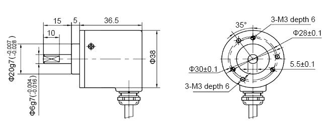
Dimension (unit: mm)
Application
Tips: How to use a incremental encoder?
- Incremental rotary encoders have difference on resolution, the number can be from 6 to 5400 or higher, then the larger number of pulse, the higher the resolution. This is one of important basis for selection.
- Incremental encoder usually has three signal outputs: A, B and Z, generally adopt TTL level, A pulse is in the front while B pulse is after it. There is 90° of skewing between A pulse and B pulse, each circle issue a Z pulse, which can be used as a reference mechanical zero. We usually detect direction by judging whether A ahead of B, or B ahead of A, but the specific situation depends on the product description.
- Using PLC to collect data, we can choose high-speed counting module; when using IPC to collect data, we can choose high-speed counting board; when using SCM to collect data, we can choose the input port of optical coupler.
- It is recommended to use B pulse as forward pulse, A pulse as reverse pulse and Z as original point zero pulse.
Only registered users can write reviews
Related products

Incremental Rotary Encoder, Blind Shaft, 360 ppr
ATO-IRE-360PB
$167.94
Incremental rotary encoder has 360 ppr resolution, 38mm shell diameter and 8mm blind shaft diameter. Cheap optical rotary encoder with optional output mode, small installation dimension, high quality, manufacturer direct sale.

Incremental Rotary Encoder, Shaft, 500 ppr
ATO-IRE-500PS
$142.22
Favourable price optical encoder has 6mm diameter stainless steel shaft, 38mm shell diameter, 500 ppr resolution, high reliability, high quality, several output modes to choose, manufacturer direct sale.

Incremental Rotary Encoder, Shaft, 600 ppr
ATO-IRE-600PS
$181.59
Cheap optical rotary encoder adopts stainless steel shaft, square flange and plug edge output mode. The diameter of shaft is 15mm. The diameter of shell is 58mm. Incremental rotary encoder has 600 ppr resolution, high reliability, high quality, optional output mode and working voltage, manufacturer direct sale.

Incremental Rotary Encoder, Blind Shaft, 800 ppr
ATO-IRE-800PB
$237.46
Low priced optical incremental encoder adopts blind shaft and cable edge output mode. Rotay encoder with 800 rrp resolution, 8mm shaft diameter, 52mm shell diameter, has small installation dimension, high reliability, high quality, 6 output modes to choose, manufacturer direct sale.