Digital Stepper Motor Driver, 2 Phase, DC 18V ~ 36V

$59.37
Digital stepper driver powered by DC 18V ~ 36V power supply, adjustable drive current from 0.3A to 2.3A, capable of driving Nema 8, 11, 14, 17 hybrid 2 phase stepper motors. This stepper motor controller can realize precise position control even without a feedback system.
SKU: ATO-STEP-M302A
*
Free Shipping
Delivery date: 6-12 days

Low price micro digital stepper motor driver for sale. It offers adjustable current control and multiple step resolutions, allowing the hybrid bipolar stepper motor to be driven with simple step and direction inputs.

Features

  • Digital stepper motor driver is high performance, low price, low noise and good stability.
  • Optically isolated signal input.
  • Continuously adjustable drive current from 0.3 ~ 2.3A.
  • When the pulse stops exceeds 100ms, the coil current is automatically halved.
  • Low repair rate and high reliability.
  • Average current control, 2 phase sinusoidal current drive output.
  • Suitable for two phase Nema 8, Nema 11, Nema 14, Nema 17 stepper motor.

Specification

ModelATO-FYQM302A
Matched MotorNema 17 2 Phase Stepper Motor
VoltageDC 18V ~ 36V
Drive Current0.3A ~ 2.3A 8 Channels
Microstepping Setting25600 steps/rev  16 Channels
Hightest  Pulse Frequency100Kpps
CertificationCE, FCC, RoHS
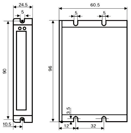
Dimensions96 x 60.5 x 24.5mm
Weight0.5kg
Function Description
FunctionsOperation Instructions
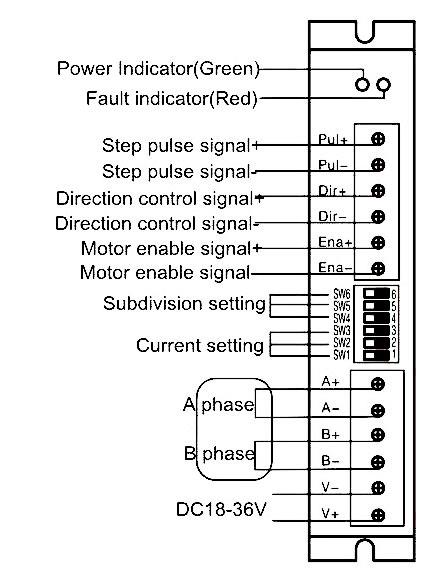
PWRPower Indicating LampWhen the driver is powered on, the green light is always on.
ALARMOvercurrent/Undervoltage IndicatorWhen the overvoltage and overcurrent faults occur, the red light is always on.
PUL+Positive End of Control Pulse SignalConnect to signal power,+5V to +24V can be driven.
PUL-Negative End of Control Pulse SignalThe falling edge is valid, and the motor takes one step whenever the pulse changes from high to low. Input resistance 220Ω. Requirements: low level 0 to 0.5V, high level 4 to 5V, Pulse charge >2.5us.
DIR+Positive End of Directional SignalConnect to signal power,+5V to +24V can be driven.
DIR-Negative End of Directional SignalUsed to change the direction of the motor.Input resistance 220Ω. Requirements: low level 0 to 0.5V, high level 4 to 5V, Pulse charge >2.5us.
ENA+Positive End of Enabling SignalConnect to signal power,+5V to +24V can be driven.
ENA-Negative End of Enabling SignalWhen it is valid (low level), the motor coil current is turned off, the driver stops working, and the motor is in a free state.

Operating Current Setting

Peak CurrentSW1SW2SW3
0.3Aononon
0.6Aoffonon
0.9Aonoffon
1.2Aoffoffon
1.4Aononoff
1.7Aoffonoff
2.0Aonoffoff
2.3Aoffoffoff

Microstep Segmentation Setting

Pulse/RevoSW4SW5SW6
200ononon
400offonon
800onoffon
1600offoffon
3200ononoff
6400offonoff
12800onoffoff
25600offoffoff

Dimensions (Unit: mm)

Dimensions of 2 Phase DC 18V-36V Digital Stepper Motor Driver

Wiring Diagram

Wiring Diagram of 2 Phase DC 18V-36V Digital Stepper Motor Driver

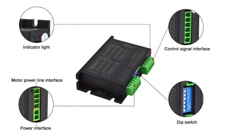
Details

2 Phase Digital Stepper Motor Driver 18v~36v Details

Tips: Functions of stepper motor driver

The digital stepper motor driver is an actuator that converts electrical pulses into angular displacement. In the use of the motor, the driver receives a pulse signal, and drives the motor to rotate a fixed angle in the set direction, and rotate step by step at a fixed angle. The stepper motor driver can control the angular displacement by controlling the number of pulses, and can also control the speed and acceleration of the motor's rotation by controlling the pulse frequency. Through these two methods, the positioning control and speed control are realized respectively. The entire stepper motor drive system is composed of two parts: a motor and a driver. While the performance of the drive system depends on the performance of the motor itself, it also depends on the pros and cons of the drive stage.

How to control a stepper motor using a PLC and HMI?
This video shows you how to configure a PLC, HMI, motor driver, and proximity sensor to perform Origin Return (OPR) control of a stepper motor.

Common Stepper Motor Troubleshooting Problems and Tips
In this video, 9 common problems that can occur with stepper motors are discussed, and expert advice is provided for diagnosing and effectively resolving these problems. If you have ever experienced problems with your stepper motor or want to be prepared for any future problems, this video is a must watch.

Product reviews
Works perfectly.
5
Maria
Avatar
4/14/2022 8:00 PM
This is in my opinion a good value for the money. Exactly what I needed. Arrived quickly and efficiently! I wanted to drive a Nema 17 2 phase stepper motor stepper with my 3D printer, this made that possible. It exhibited good accuracy.
Was this review helpful? Yes No (0/0)
Write your review
  • Only registered users can write reviews
*
*
  • Bad
  • Excellent
*
*
*
*

Low price micro digital stepper motor driver for sale. It offers adjustable current control and multiple step resolutions, allowing the hybrid bipolar stepper motor to be driven with simple step and direction inputs.

Features

  • Digital stepper motor driver is high performance, low price, low noise and good stability.
  • Optically isolated signal input.
  • Continuously adjustable drive current from 0.3 ~ 2.3A.
  • When the pulse stops exceeds 100ms, the coil current is automatically halved.
  • Low repair rate and high reliability.
  • Average current control, 2 phase sinusoidal current drive output.
  • Suitable for two phase Nema 8, Nema 11, Nema 14, Nema 17 stepper motor.

Specification

ModelATO-FYQM302A
Matched MotorNema 17 2 Phase Stepper Motor
VoltageDC 18V ~ 36V
Drive Current0.3A ~ 2.3A 8 Channels
Microstepping Setting25600 steps/rev  16 Channels
Hightest  Pulse Frequency100Kpps
CertificationCE, FCC, RoHS
Dimensions96 x 60.5 x 24.5mm
Weight0.5kg
Function Description
FunctionsOperation Instructions
PWRPower Indicating LampWhen the driver is powered on, the green light is always on.
ALARMOvercurrent/Undervoltage IndicatorWhen the overvoltage and overcurrent faults occur, the red light is always on.
PUL+Positive End of Control Pulse SignalConnect to signal power,+5V to +24V can be driven.
PUL-Negative End of Control Pulse SignalThe falling edge is valid, and the motor takes one step whenever the pulse changes from high to low. Input resistance 220Ω. Requirements: low level 0 to 0.5V, high level 4 to 5V, Pulse charge >2.5us.
DIR+Positive End of Directional SignalConnect to signal power,+5V to +24V can be driven.
DIR-Negative End of Directional SignalUsed to change the direction of the motor.Input resistance 220Ω. Requirements: low level 0 to 0.5V, high level 4 to 5V, Pulse charge >2.5us.
ENA+Positive End of Enabling SignalConnect to signal power,+5V to +24V can be driven.
ENA-Negative End of Enabling SignalWhen it is valid (low level), the motor coil current is turned off, the driver stops working, and the motor is in a free state.

Operating Current Setting

Peak CurrentSW1SW2SW3
0.3Aononon
0.6Aoffonon
0.9Aonoffon
1.2Aoffoffon
1.4Aononoff
1.7Aoffonoff
2.0Aonoffoff
2.3Aoffoffoff

Microstep Segmentation Setting

Pulse/RevoSW4SW5SW6
200ononon
400offonon
800onoffon
1600offoffon
3200ononoff
6400offonoff
12800onoffoff
25600offoffoff

Dimensions (Unit: mm)

Dimensions of 2 Phase DC 18V-36V Digital Stepper Motor Driver

Wiring Diagram

Wiring Diagram of 2 Phase DC 18V-36V Digital Stepper Motor Driver

Details

2 Phase Digital Stepper Motor Driver 18v~36v Details

Tips: Functions of stepper motor driver

The digital stepper motor driver is an actuator that converts electrical pulses into angular displacement. In the use of the motor, the driver receives a pulse signal, and drives the motor to rotate a fixed angle in the set direction, and rotate step by step at a fixed angle. The stepper motor driver can control the angular displacement by controlling the number of pulses, and can also control the speed and acceleration of the motor's rotation by controlling the pulse frequency. Through these two methods, the positioning control and speed control are realized respectively. The entire stepper motor drive system is composed of two parts: a motor and a driver. While the performance of the drive system depends on the performance of the motor itself, it also depends on the pros and cons of the drive stage.

Product reviews
Works perfectly.
5
Maria
Avatar
4/14/2022 8:00 PM
This is in my opinion a good value for the money. Exactly what I needed. Arrived quickly and efficiently! I wanted to drive a Nema 17 2 phase stepper motor stepper with my 3D printer, this made that possible. It exhibited good accuracy.
Was this review helpful? Yes No (0/0)
Only registered users can write reviews
Customers who bought this item also bought

1 in 4/6/10/12 out Terminal Junction Box

ATO-TJB-1IN
$26.31
The provided is a junction box with terminal block, which can be used for various types of wire connections. 1 in 4/6/10/12 out terminal junction box has excellent electrical conductivity and high tensile strength, 4~35mm2 mainline range, 0.75~10mm2 outlet range, suitable for household appliances, electrical industries, distribution cabinets, distribution boxes, mechanical equipment factories, shipyards, etc.

Circular Connector, 2/3/4/5/6/7/8 Pin, M12

ATO-CIRCN-XS12
$49.21
Circular connector is used for connecting component & cable, cable & cable, easy to seal, insert and dismantle. Circular connector has 2/3/4/5/6/7/8 pin, female/male plug & socket to select.

Miniature Slip Ring Connector, 22mm, 2-36 Wires, 2A/5A/10A/30A

ATO-MNTSR-220
$72.92
Miniature slip ring connector uses a capsule design with 22mm outer diameter. Transmission circuit of standard model can select 2A/5A/10A/30A per wire, the number of circuits are optional in 2 wires~36 wires. Other currents and circuits quantities are customizable. Mounting method is A-type flange or no flange.