Clamp-on Ground Resistance Tester, 0.01-1000Ω

$869.23
Clamp-on earth ground resistance tester is capacble of peforming grounding resistance testing accurately and simply, measuring range from 0.01Ω to 1000Ω. Leakage current measurement is also available. Rugged, durable, easy to use, ideal for outdoor work.
SKU: ATO-GRT-UT273
*
Free Shipping
Delivery date: 6-12 days

Clamp-on earth ground tester can measure the ground resistance from 0.01Ω to 1000Ω. With the the clamp on the loop, the meter can get the resistance value safely and quickly without disconnecting circuit ground lines or in needless of auxiliary electrodes. This clamp-on ground resistance tester is durable and accurate, suitable for grounding system measurement of electric power system, telecommunication, meteorology, oil field, building and other fields.

Specification

ModelATO-GRT-UT273ATO-GRT-UT275
Earth Ground Resistance (Ω)0.01Ω~0.099Ω±(1%+0.01)±(1%+0.01)
0.1Ω~0.99Ω±(1%+0.01)±(1%+0.01)
1.0Ω~49.9Ω±(1.5%+0.1)±(1.5%+0.1)
50Ω~99.5Ω±(2%+0.5)±(2%+0.5)
100Ω~199Ω±(3%+1)±(3%+1)
200Ω~395Ω±(10%+5)±(10%+5)
400Ω~590Ω±(20%+10)±(20%+10)
600~1000Ω±(25%+20)±(25%+20)
Leakage Current (A)0.00mA~299mA—±(2.5%+2mA)
0.30A~2.99A—±(2.5%+100mA)
3A~30A—±(2.5%+100mA)
FeaturesDisplay9999 counts9999 counts
Auto range√√
Jaw opening28mm28mm
Auto power off√√
Low battery indication√√
Data hold√√
Data storage30 sets30 sets
Data recall√√
LCD backlight√√
Auto calibration√√
GeneralPower supply1.5V battery (LR6) x 4
Display size47mm x 28.5mm
Operating temperature0℃ ~ 40℃
Operating relative humidity10%~90%RH non-condensing
Operating altitude≤2000m
Product weight1.5kg
Product size293mm x 90mm x 66mm
Standard accessories *Batteries, test ring, carrying box

Note: * Batteries are Not Included for air shippment.

Details
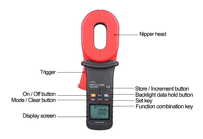
Clamp on Ground Resistance Tester Details

Tips: Measuring principle of clamp-on ground resistance tester

1. Resistance measurement principle

The basic principle of measuring ground resistance with a clamp-on earth ground tester is measuring loop resistance. The jaw part of the clamp meter is composed of voltage coil and current coil. The voltage coil provides the excitation signal and induces a potential E on the circuit under test. Under the action of potential E, current I will be generated in the circuit under test. The clamp ground tester measures E and I, and through the formula R=E/I, the measured resistance R can be obtained.

2. Principle of current measurement

The basic principle of measuring the current of the clamp-on ground resistance meter is the same as that of the current transformer. AC current I of the measured wire generates an induced current I1 through the current magnetic ring and current coil of the clamp. I1 is measured by the clamp meter. The measured current I can be obtained by formula I=n* I1 (n is the turns ratio of the coil between the auxiliary side and the original side).

Insulation Diagnostics on Motors with an Insulation Resistance Tester

This advanced insulation tester is designed to measure the insulation resistance of an electrical system, providing valuable insight into its quality and integrity. It also has the ability to measure AC voltage, making it a versatile tool for electrical professionals.

Product reviews
Can this tester be calibrated?
5
Stephen
Avatar
4/24/2022 7:54 PM
Well, before I order this tester, I want to sure can this clamp-on ground resistance tester be calibrated as required by some clients? Is it easy to calibrated? I hope you can give me a favor.
Was this review helpful? Yes No (0/0)
ATO Responded
Yes, you can calibrate it and it is quite easy.
Great price on a well performing instrument
5
Steyn
Avatar
5/7/2022 3:30 AM
I received the  ground resistance tester very quickly after placing the order, I have a project to go back to test the ground rods that were not tested at the time of installation, It is easy to use and very accurate.
Was this review helpful? Yes No (0/0)
Write your review
  • Only registered users can write reviews
*
*
  • Bad
  • Excellent
*
*
*
*

Clamp-on earth ground tester can measure the ground resistance from 0.01Ω to 1000Ω. With the the clamp on the loop, the meter can get the resistance value safely and quickly without disconnecting circuit ground lines or in needless of auxiliary electrodes. This clamp-on ground resistance tester is durable and accurate, suitable for grounding system measurement of electric power system, telecommunication, meteorology, oil field, building and other fields.

Specification

ModelATO-GRT-UT273ATO-GRT-UT275
Earth Ground Resistance (Ω)0.01Ω~0.099Ω±(1%+0.01)±(1%+0.01)
0.1Ω~0.99Ω±(1%+0.01)±(1%+0.01)
1.0Ω~49.9Ω±(1.5%+0.1)±(1.5%+0.1)
50Ω~99.5Ω±(2%+0.5)±(2%+0.5)
100Ω~199Ω±(3%+1)±(3%+1)
200Ω~395Ω±(10%+5)±(10%+5)
400Ω~590Ω±(20%+10)±(20%+10)
600~1000Ω±(25%+20)±(25%+20)
Leakage Current (A)0.00mA~299mA—±(2.5%+2mA)
0.30A~2.99A—±(2.5%+100mA)
3A~30A—±(2.5%+100mA)
FeaturesDisplay9999 counts9999 counts
Auto range√√
Jaw opening28mm28mm
Auto power off√√
Low battery indication√√
Data hold√√
Data storage30 sets30 sets
Data recall√√
LCD backlight√√
Auto calibration√√
GeneralPower supply1.5V battery (LR6) x 4
Display size47mm x 28.5mm
Operating temperature0℃ ~ 40℃
Operating relative humidity10%~90%RH non-condensing
Operating altitude≤2000m
Product weight1.5kg
Product size293mm x 90mm x 66mm
Standard accessories *Batteries, test ring, carrying box

Note: * Batteries are Not Included for air shippment.

Details

Clamp on Ground Resistance Tester Details

Tips: Measuring principle of clamp-on ground resistance tester

1. Resistance measurement principle

The basic principle of measuring ground resistance with a clamp-on earth ground tester is measuring loop resistance. The jaw part of the clamp meter is composed of voltage coil and current coil. The voltage coil provides the excitation signal and induces a potential E on the circuit under test. Under the action of potential E, current I will be generated in the circuit under test. The clamp ground tester measures E and I, and through the formula R=E/I, the measured resistance R can be obtained.

2. Principle of current measurement

The basic principle of measuring the current of the clamp-on ground resistance meter is the same as that of the current transformer. AC current I of the measured wire generates an induced current I1 through the current magnetic ring and current coil of the clamp. I1 is measured by the clamp meter. The measured current I can be obtained by formula I=n* I1 (n is the turns ratio of the coil between the auxiliary side and the original side).

Product reviews
Can this tester be calibrated?
5
Stephen
Avatar
4/24/2022 7:54 PM
Well, before I order this tester, I want to sure can this clamp-on ground resistance tester be calibrated as required by some clients? Is it easy to calibrated? I hope you can give me a favor.
Was this review helpful? Yes No (0/0)
ATO Responded
Yes, you can calibrate it and it is quite easy.
Great price on a well performing instrument
5
Steyn
Avatar
5/7/2022 3:30 AM
I received the  ground resistance tester very quickly after placing the order, I have a project to go back to test the ground rods that were not tested at the time of installation, It is easy to use and very accurate.
Was this review helpful? Yes No (0/0)
Only registered users can write reviews