2D Electronic Compass Module, 0°-360°, RS232/RS485/TTL/RS422

$178.16
Cost-effective 2D electronic compass module (single board) has a measurement range of 0° to 360° and high accuracy of ±1°. It supports multiple communication interfaces, including RS232, RS485, TTL, RS422 and Modbus (optional). The module has an operating temperature range of -40°C to +70°C, has good anti-magnetic interference ability, and is widely used in automation control, navigation positioning, robotics and other fields.
SKU: ATO-CPS-SCM220
*
Free Shipping
Delivery date: 6-12 days

The 2D electronic compass module (single board) uses advanced magnetic sensing technology to provide accurate heading measurement. The single board has a compact structure and is easy to integrate into embedded systems and devices.

Features

  • It is a high-precision two-dimensional electronic compass module that measures azimuth 0~360° with high reliability.
  • 2D electronic compass module uses an industrial-grade single-chip microcomputer with strong anti-interference ability and a high-precision magnetic sensor and driver chip, integrating hard magnetic and soft magnetic interference compensation technology. The electronic compass function can be easily and quickly integrated into various products.
  • The compass module is small in size and low in power consumption. It can be used in many fields such as antenna stability, vehicles, system integration, etc. High seismic resistance and high reliability also enable the compass to work normally in extremely harsh environments.

Specification

ModelATO-SCM220
Range0-360°
Accuracy1°
Working voltageDC +5V
Working temperature-40~+70℃
Working current40mA
Volume33*27*8mm (customizable)
OutputRS232/RS485/TTL/RS422/Modbus (optional)
Performance Indicators
Compass heading parametersHeading accuracy1°
Resolution0.1°
Repeatability0.3°
Heading angleNavigation tilt angle range+/-5°
Heading angle measurement range0~360°
CalibrationHard iron calibration✔
Soft iron calibration✔
Magnetic field interference calibrationone rotation of the plane (two-dimensional calibration)
Physical characteristicsDimensionsL33xW27xH8 (mm)
Weight5g
RS-232/RS485 interface connector5-pin
Interface characteristicsStartup delay<50ms
Maximum sampling rate50 times/second
RS-232 communication rate2400~19200 baud rate
RS-485 communicationOptional
TTL communicationOptional
Output formatHexadecimal
Power supplySupported voltageDC+5V
Current (maximum)40mA
Operating mode30mA
EnvironmentStorage range-40℃~+125℃
Operating temperature-40℃~+70℃
Vibration resistance2500g

Note: The default horizontal installation (when the compass is placed horizontally, the roll and pitch angle outputs are zero degrees), and the connector needs to be installed vertically downward (when the compass is placed vertically downward, the roll and pitch angle outputs are zero degrees). Please specify when ordering.

Dimension (mm)
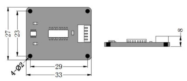
2d electronic compass module dimension

Electrical Connection

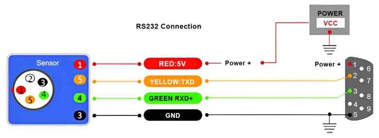
  • RS232 Wiring Definition
Line Color FunctionREDWHITEBLACKGREENYELLOW
12345
VCCNCGNDRXDTXD

2d electronic compass sensor rs232-wiring

  • RS485 and Modbus Wiring Definition
Line Color FunctionREDWHITEBLACKGREENYELLOW
12345
VCCNCGND(B, D+)(A, D+)
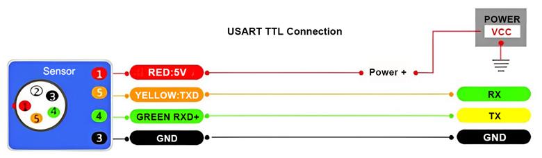
  • TTL Wiring Definition
Line Color FunctionREDWHITEBLACKGREENYELLOW
12345
VCCNCGNDRXDTXD

2d electronic compass sensor ttl wiring

  • RS422 Wiring Definition
Line Color FunctionREDBLACKGREENYELLOWWHITEBROWN
123456
VCCGNDRXD- (B-)RXD+ (A+)TXD+ (A+)TXD- (B-)


Applications

2d electronic compass application

Installation

2d electronic compass module installations

Tips: Precautions for installing 2D electronic compass module

Although the SCM220 electronic compass module can compensate for magnetic interference, users should choose an environment with minimal magnetic interference for installation and use. It is recommended to install 2D electronic compass module away from iron, nickel, magnets, engines, and other magnetic materials. If these magnetic sources are present nearby, maintain a minimum distance of 0.5 meters. To ensure optimal measurement accuracy, use non-magnetic screwdrivers and non-ferrous screws during installation. Strong magnetic materials (such as magnets and electric motors) should be kept at least 10 cm away from the compass, as closer proximity may cause irreversible degradation of measurement accuracy.

Each electronic compass module comes with a 10 cm cable, with an optional length depending on user needs. While 2D electronic compass module can compensate for magnetic deviation in a stable magnetic environment, it cannot compensate for changing magnetic interference. For example, wires carrying DC current generate a magnetic field, and if the current changes, the magnetic field strength will vary accordingly. Batteries are another potential source of changing interference. Since each installation environment will have a different magnetic field, users must evaluate the feasibility of installation in their specific environment.

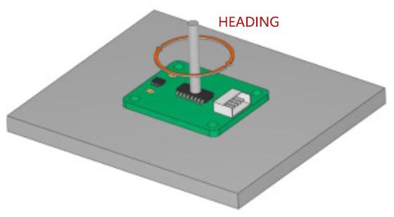
The compass module has a heading accuracy of 1°, which has been rigorously verified. Proper scientific testing methods are equally crucial. Our recommended testing method is to mount it on a vertical aluminum (or other non-magnetic material) rod for heading accuracy measurement. Ensure the rod is perpendicular to the rotating platform, and minimize the influence of large external magnetic fields during the test.

Product reviews
Reliable and accurate
5
Mike
Avatar
10/22/2025 8:54 PM
This compass module provides stable heading data in our mobile diagnostic devices. Its anti-interference capability ensures consistent performance near metal components. Compact size and multiple interfaces simplify installation.
Was this review helpful? Yes No (0/0)
Write your review
  • Only registered users can write reviews
*
*
  • Bad
  • Excellent
*
*
*
*

The 2D electronic compass module (single board) uses advanced magnetic sensing technology to provide accurate heading measurement. The single board has a compact structure and is easy to integrate into embedded systems and devices.

Features

  • It is a high-precision two-dimensional electronic compass module that measures azimuth 0~360° with high reliability.
  • 2D electronic compass module uses an industrial-grade single-chip microcomputer with strong anti-interference ability and a high-precision magnetic sensor and driver chip, integrating hard magnetic and soft magnetic interference compensation technology. The electronic compass function can be easily and quickly integrated into various products.
  • The compass module is small in size and low in power consumption. It can be used in many fields such as antenna stability, vehicles, system integration, etc. High seismic resistance and high reliability also enable the compass to work normally in extremely harsh environments.

Specification

ModelATO-SCM220
Range0-360°
Accuracy1°
Working voltageDC +5V
Working temperature-40~+70℃
Working current40mA
Volume33*27*8mm (customizable)
OutputRS232/RS485/TTL/RS422/Modbus (optional)
Performance Indicators
Compass heading parametersHeading accuracy1°
Resolution0.1°
Repeatability0.3°
Heading angleNavigation tilt angle range+/-5°
Heading angle measurement range0~360°
CalibrationHard iron calibration✔
Soft iron calibration✔
Magnetic field interference calibrationone rotation of the plane (two-dimensional calibration)
Physical characteristicsDimensionsL33xW27xH8 (mm)
Weight5g
RS-232/RS485 interface connector5-pin
Interface characteristicsStartup delay<50ms
Maximum sampling rate50 times/second
RS-232 communication rate2400~19200 baud rate
RS-485 communicationOptional
TTL communicationOptional
Output formatHexadecimal
Power supplySupported voltageDC+5V
Current (maximum)40mA
Operating mode30mA
EnvironmentStorage range-40℃~+125℃
Operating temperature-40℃~+70℃
Vibration resistance2500g

Note: The default horizontal installation (when the compass is placed horizontally, the roll and pitch angle outputs are zero degrees), and the connector needs to be installed vertically downward (when the compass is placed vertically downward, the roll and pitch angle outputs are zero degrees). Please specify when ordering.

Dimension (mm)

2d electronic compass module dimension

Electrical Connection

  • RS232 Wiring Definition
Line Color FunctionREDWHITEBLACKGREENYELLOW
12345
VCCNCGNDRXDTXD

2d electronic compass sensor rs232-wiring

  • RS485 and Modbus Wiring Definition
Line Color FunctionREDWHITEBLACKGREENYELLOW
12345
VCCNCGND(B, D+)(A, D+)
  • TTL Wiring Definition
Line Color FunctionREDWHITEBLACKGREENYELLOW
12345
VCCNCGNDRXDTXD

2d electronic compass sensor ttl wiring

  • RS422 Wiring Definition
Line Color FunctionREDBLACKGREENYELLOWWHITEBROWN
123456
VCCGNDRXD- (B-)RXD+ (A+)TXD+ (A+)TXD- (B-)


Applications

2d electronic compass application

Installation

2d electronic compass module installations

Tips: Precautions for installing 2D electronic compass module

Although the SCM220 electronic compass module can compensate for magnetic interference, users should choose an environment with minimal magnetic interference for installation and use. It is recommended to install 2D electronic compass module away from iron, nickel, magnets, engines, and other magnetic materials. If these magnetic sources are present nearby, maintain a minimum distance of 0.5 meters. To ensure optimal measurement accuracy, use non-magnetic screwdrivers and non-ferrous screws during installation. Strong magnetic materials (such as magnets and electric motors) should be kept at least 10 cm away from the compass, as closer proximity may cause irreversible degradation of measurement accuracy.

Each electronic compass module comes with a 10 cm cable, with an optional length depending on user needs. While 2D electronic compass module can compensate for magnetic deviation in a stable magnetic environment, it cannot compensate for changing magnetic interference. For example, wires carrying DC current generate a magnetic field, and if the current changes, the magnetic field strength will vary accordingly. Batteries are another potential source of changing interference. Since each installation environment will have a different magnetic field, users must evaluate the feasibility of installation in their specific environment.

The compass module has a heading accuracy of 1°, which has been rigorously verified. Proper scientific testing methods are equally crucial. Our recommended testing method is to mount it on a vertical aluminum (or other non-magnetic material) rod for heading accuracy measurement. Ensure the rod is perpendicular to the rotating platform, and minimize the influence of large external magnetic fields during the test.

Product reviews
Reliable and accurate
5
Mike
Avatar
10/22/2025 8:54 PM
This compass module provides stable heading data in our mobile diagnostic devices. Its anti-interference capability ensures consistent performance near metal components. Compact size and multiple interfaces simplify installation.
Was this review helpful? Yes No (0/0)
Only registered users can write reviews