2-phase Digital Stepper Driver for Nema 11, 14, 17 Stepper Motor

$89.54
ATODSP42 is a closed-loop digital 2-phase stepper motor driver which adopts latest 32-bit DSP control technology, 18-40V DC power supply. Suitable for any small and medium automatic equipment. All the 2 phase Nema 11, 14, 17 stepper motors will work perfectly with this type of stepper driver.
SKU: ATO-STEP-D1114
*
Free Shipping
Delivery date: 6-12 days

2-phase digital stepper driver, 18-40V DC, 0.5-2.2A for Nema 11, 14, 17 2 phase stepper motor, manufacturer direct sale.

Features:

  • Low motor vibration, low noise, no loss of step.
  • Optical isolation, difference signal input.
  • Automatic motor parameter identification.
  • Vector control, ultra-low heating.
  • Offer 12-24v control signal interface.
  • Step and direction control.
  • Fast response, no delay and zero setting time.
  • Much lower cost than traditional servo systems.
  • No torque reservation.

Specifications

Basics Information
ModelATODSP42
Size86 x 55.5 x 20.5 mm
Phase2
MaterialStainless Steel
Mounting Hole Distance78 mm
Max Input Power100 W
Input Voltage Range18-40V DC
Output Current0.5-2.2 A
Control ModeStep & Direction
Function Description
FunctionsOperation Instructions
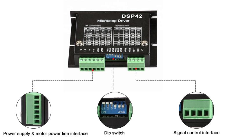
Signal InterfacePULPUL+ is the positive end of the control pulse signal
PUL- is the negative end of the control pulse signal
DIRDIR+ is the positive end of directional signal
DIR- is the negative end of directional signal
ENAENA+ is the positive end of enabling signal
ENA+ is the negative end of enabling signal
OPTOIn order to enhance the anti-interference ability of the pulse signal, the control signal VCC-5V or 24V is optional for OPTO, and no series resistance is required.
Motor InterfaceAA+ is connected with the positive end of the A phase winding of the stepping motor
A- is connected with the negative end of the A phase winding of the stepping motor
BB+ is connected with the positive end of the B phase winding of the stepping motor
B- is connected with the negative end of the B phase winding of the stepping motor
When the A and B two phase windings are switched, the motor direction is reversed
Indicator Light1. The green light is the power indicating lamp. When the drive is powered on, the green light is always on.
2. The red light is the fault indicating lamp. When the overvoltage and overcurrent faults occur, the trouble lamp is always on.
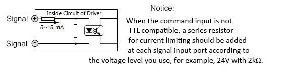
Note: The default input signal is 5V pulse signal. When 24V input signal is required, please in series with1.8-2kΩ resistance.

Switch of Options

Peak Output CurrentREF Output CurrentSW1SW2SW3
DefaultONONON
0.5A0.35AOFFONON
0.7A0.5AONOFFON
1A0.7AOFFOFFON
1.3A0.9AONONOFF
1.6A1.2AOFFONOFF
1.9A1.4AONOFFOFF
2.2A1.6AOFFOFFOFF

Micro Step Selection

PUL/REVSW5SW6
800ONON
1600OFFON
3200ONOFF
6400OFFOFF

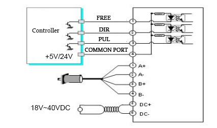
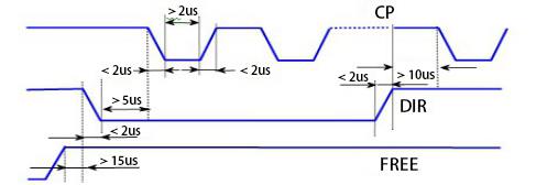
Driver Wiring Diagram
DSP42 driver wiring diagram
Driver Wiring Diagram
driver circuit
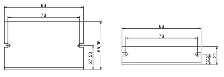
Installation Size (Unit: mm)
DSP42 dimension

Details

0.5A-2.2A Closed Loop Stepper Motor Driver Details

Tips: How to determine the DC supply power of stepper motor driver?
A. Determination of voltage
Supply voltage of hybrid stepper motor driver is generally a wide range (e.g.: the supply voltage of ATODSP42 is 18-40VDC). The power voltage is generally selected according to the working speed and response requirement. However, if the working speed and response requirement of motor is fast, the voltage value also should be high. However, the ripple wave of power voltage also cannot exceed maximum input voltage of driver, or driver may be destroyed.
B. Determination of current
The supply current is generally determined according to the output current I of the driver. If linear power is used, the power current is generally 1.1-1.3 times of I. If the switch power is used, the power current is generally 1.5-2.0 times of I.

How to control a stepper motor using a PLC and HMI?
This video shows you how to configure a PLC, HMI, motor driver, and proximity sensor to perform Origin Return (OPR) control of a stepper motor.

Common Stepper Motor Troubleshooting Problems and Tips
In this video, 9 common problems that can occur with stepper motors are discussed, and expert advice is provided for diagnosing and effectively resolving these problems. If you have ever experienced problems with your stepper motor or want to be prepared for any future problems, this video is a must watch.

Product reviews
Can this 2-phase digital stepper motor control a NEMA8 stepper motor?
5
Martink
Avatar
11/2/2021 11:54 PM
Could your DSP42 stepper motor drive control a NEMA 8 stepper?
Was this review helpful? Yes No (0/0)
ATO Responded
Yes, this DSP42 controller can be used for NEMA 11, 14, 17 stepper motor, so it can be used for NEMA 8 Motor, but it would be better to send us your specific parameters of NEMA 8 Motor for more confirmation.
Digital stepper driver works great!
5
Guthrie
Avatar
5/25/2022 1:38 AM
I bought this 2-phase digital stepper driver to use an old stepper motor from a 3D Printer for a couple of projects including a cup turner for my wife's vinyl business. I immediately noticed that it was great quality for the low price compared to other stores. Everything works great!
Was this review helpful? Yes No (0/0)
Write your review
  • Only registered users can write reviews
*
*
  • Bad
  • Excellent
*
*
*
*

2-phase digital stepper driver, 18-40V DC, 0.5-2.2A for Nema 11, 14, 17 2 phase stepper motor, manufacturer direct sale.

Features:

  • Low motor vibration, low noise, no loss of step.
  • Optical isolation, difference signal input.
  • Automatic motor parameter identification.
  • Vector control, ultra-low heating.
  • Offer 12-24v control signal interface.
  • Step and direction control.
  • Fast response, no delay and zero setting time.
  • Much lower cost than traditional servo systems.
  • No torque reservation.

Specifications

Basics Information
ModelATODSP42
Size86 x 55.5 x 20.5 mm
Phase2
MaterialStainless Steel
Mounting Hole Distance78 mm
Max Input Power100 W
Input Voltage Range18-40V DC
Output Current0.5-2.2 A
Control ModeStep & Direction
Function Description
FunctionsOperation Instructions
Signal InterfacePULPUL+ is the positive end of the control pulse signal
PUL- is the negative end of the control pulse signal
DIRDIR+ is the positive end of directional signal
DIR- is the negative end of directional signal
ENAENA+ is the positive end of enabling signal
ENA+ is the negative end of enabling signal
OPTOIn order to enhance the anti-interference ability of the pulse signal, the control signal VCC-5V or 24V is optional for OPTO, and no series resistance is required.
Motor InterfaceAA+ is connected with the positive end of the A phase winding of the stepping motor
A- is connected with the negative end of the A phase winding of the stepping motor
BB+ is connected with the positive end of the B phase winding of the stepping motor
B- is connected with the negative end of the B phase winding of the stepping motor
When the A and B two phase windings are switched, the motor direction is reversed
Indicator Light1. The green light is the power indicating lamp. When the drive is powered on, the green light is always on.
2. The red light is the fault indicating lamp. When the overvoltage and overcurrent faults occur, the trouble lamp is always on.
Note: The default input signal is 5V pulse signal. When 24V input signal is required, please in series with1.8-2kΩ resistance.

Switch of Options

Peak Output CurrentREF Output CurrentSW1SW2SW3
DefaultONONON
0.5A0.35AOFFONON
0.7A0.5AONOFFON
1A0.7AOFFOFFON
1.3A0.9AONONOFF
1.6A1.2AOFFONOFF
1.9A1.4AONOFFOFF
2.2A1.6AOFFOFFOFF

Micro Step Selection

PUL/REVSW5SW6
800ONON
1600OFFON
3200ONOFF
6400OFFOFF

Driver Wiring Diagram
DSP42 driver wiring diagram
Driver Wiring Diagram
driver circuit
Installation Size (Unit: mm)
DSP42 dimension

Details

0.5A-2.2A Closed Loop Stepper Motor Driver Details

Tips: How to determine the DC supply power of stepper motor driver?
A. Determination of voltage
Supply voltage of hybrid stepper motor driver is generally a wide range (e.g.: the supply voltage of ATODSP42 is 18-40VDC). The power voltage is generally selected according to the working speed and response requirement. However, if the working speed and response requirement of motor is fast, the voltage value also should be high. However, the ripple wave of power voltage also cannot exceed maximum input voltage of driver, or driver may be destroyed.
B. Determination of current
The supply current is generally determined according to the output current I of the driver. If linear power is used, the power current is generally 1.1-1.3 times of I. If the switch power is used, the power current is generally 1.5-2.0 times of I.

Product reviews
Can this 2-phase digital stepper motor control a NEMA8 stepper motor?
5
Martink
Avatar
11/2/2021 11:54 PM
Could your DSP42 stepper motor drive control a NEMA 8 stepper?
Was this review helpful? Yes No (0/0)
ATO Responded
Yes, this DSP42 controller can be used for NEMA 11, 14, 17 stepper motor, so it can be used for NEMA 8 Motor, but it would be better to send us your specific parameters of NEMA 8 Motor for more confirmation.
Digital stepper driver works great!
5
Guthrie
Avatar
5/25/2022 1:38 AM
I bought this 2-phase digital stepper driver to use an old stepper motor from a 3D Printer for a couple of projects including a cup turner for my wife's vinyl business. I immediately noticed that it was great quality for the low price compared to other stores. Everything works great!
Was this review helpful? Yes No (0/0)
Only registered users can write reviews